Glass Tempering Furnace Buying Guide: 2026 B2B Specs
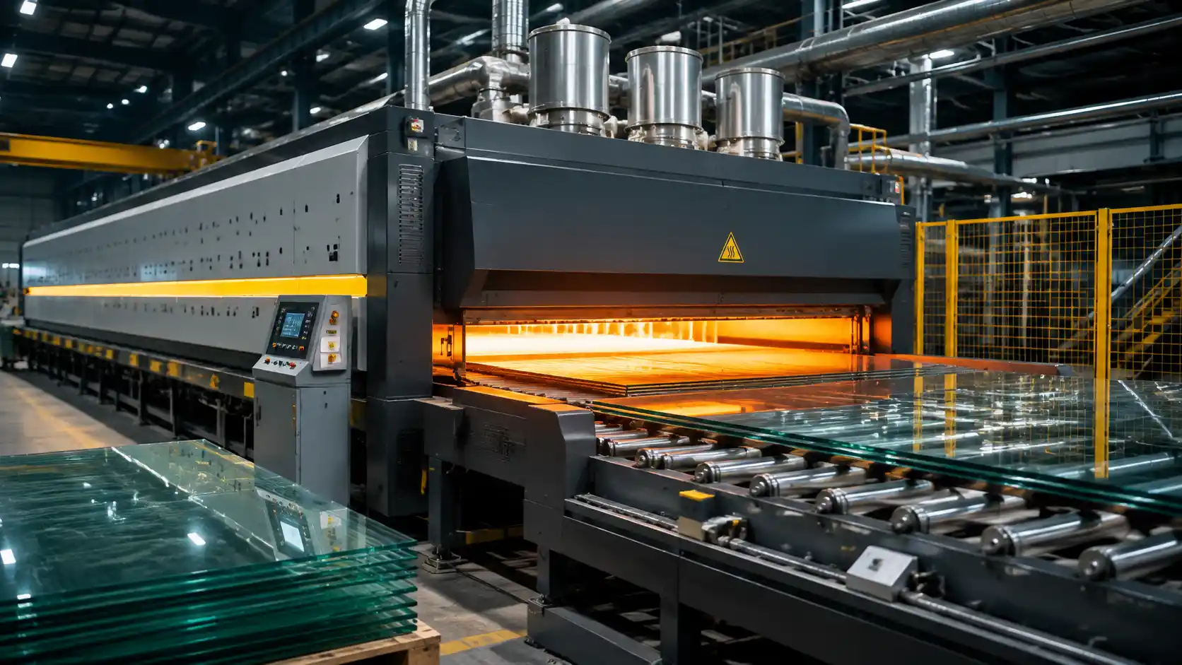
Investing in a commercial glass tempering furnace represents one of the largest capital expenditures for any glass fabrication plant. Whether expanding facility capacity, replacing legacy machinery, or setting up a new processing plant, selecting the right equipment directly dictates your plant’s yield, energy overhead, optical clarity, and capability to process advanced soft-coated Low-E glass.
In the North American market, architectural building standards such as ASTM C1048 (Type T – Fully Tempered) demand precise surface compressive stress (greater than or equal to 10,000 psi / 69 MPa) and strict control over optical distortion like roller wave, bow, and warp. Meeting these technical requirements consistently while maintaining low operational costs requires a thorough understanding of furnace mechanics, heating distribution, quenching blowers, and capacity planning.
1. Capacity Planning: Calculating Required Furnace Throughput
Before evaluating heating mechanics or automation specs, plant engineers must define the required hourly production capacity. Sizing a furnace purely on peak theoretical output often leads to underutilized capital or production bottlenecks during shift changes.
The Required Throughput Formula
To determine the minimum required hourly throughput for your plant, use the following calculation:
Required Hourly Throughput (sq ft/hr) = Target Daily Production Demand (sq ft) / (Available Operating Hours x Overall Equipment Effectiveness)
Variables Explained:
- Daily Glass Demand: Total square feet (or square meters) of glass scheduled for tempering per day.
- Available Operating Hours: Active production hours per day (e.g., two 8-hour shifts = 16 hours).
- Overall Equipment Effectiveness (OEE): A realistic factor representing loading bed utilization, heating cycle variations, and minor stops (typically 0.75 to 0.85 for well-managed lines).
Example Calculation:
A US glass fabricator needs to produce 12,000 sq ft of 1/4″ (6 mm) clear and Low-E tempered glass per day across two 8-hour shifts (16 hours total), operating at an estimated 80% OEE (0.80).
- Step 1: Multiply available hours by OEE: 16 hours x 0.80 = 12.8 effective hours.
- Step 2: Divide daily demand by effective hours: 12,000 sq ft / 12.8 hours = 937.5 sq ft/hour (approx. 87 m²/hour).
To comfortably hit this production target without running heating elements at continuous maximum thermal stress, the facility requires a glass tempering machine rated for at least 1,000 to 1,100 sq ft/hour for 6 mm glass.
2. Heating Technology: Forced Convection vs. Radiant Heating
The heating section is the heart of any flat glass tempering furnace. Annealed glass must be heated uniformly to approximately 620°C to 700°C (1148°F to 1292°F) before entering the quench section. How that thermal energy is delivered determines which glass types your plant can process.
Thermal Flow in Modern Forced Convection Lines:
- Top & Bottom Heating: High-temperature air jet nozzles continuously circulate heated air (620°C – 700°C) across both top and bottom glass surfaces.
- Roller Transport: Synchronized ceramic rollers transport glass smoothly through heating zones to maintain surface flatness.
- High-Pressure Quench: Variable Frequency Drive (VFD) turbo blowers rapidly chill surfaces to create compressive surface stress (≥ 10,000 psi).
Radiant Heating Furnaces
Radiant furnaces rely primarily on electric heating elements radiating heat directly onto glass surfaces. While economical for clear float, tinted, and patterned glass, radiant heating struggles with high-performance coated glass.
Because Low-Emissivity (Low-E) coatings reflect up to 90%+ of far-infrared radiation back toward top heating elements, the top surface of a Low-E panel heats significantly slower than the uncoated bottom surface. This thermal imbalance leads to severe spherical distortion, bow, and glass breakage inside the furnace.
Forced Convection Glass Tempering Furnaces
A convection glass tempering furnace utilizes high-temperature turbo blowers to force preheated, compressed air jets directly onto both top and bottom glass surfaces.
- Convection Jet Mechanics: Forced air breaks through the reflective thermal boundary layer of soft-coated Low-E glass (emissivity E ≤ 0.01, including double and triple-silver coatings).
- Heating Speed: Convection transfers thermal energy up to 30% faster than pure radiation, reducing cycle times and overall power consumption.
- Thermal Uniformity: Eliminates localized cold spots across matrix heating zones, dramatically improving glass flatness and optical clarity.
Key Buyer Takeaway: If your product line includes architectural double or triple-pane IGUs, commercial storefronts, or high-performance solar control glass, purchasing a full forced convection glass tempering furnace is mandatory.
3. Technical Specifications Comparison Matrix
When comparing proposals from a glass machinery supplier, use the comparison matrix below to establish baseline technical requirements for your target application:
| Specification Parameter | Standard Architectural Line | High-Yield Convection Line | Jumbo Architectural Line |
| Primary Heating Method | Radiant / Top Convection | Full Forced Jet Convection | Dual-Chamber Forced Convection |
| Glass Thickness Range | 4 mm – 19 mm (5/32″ to 3/4″) | 2.8 mm – 19 mm (1/8″ to 3/4″) | 5 mm – 25 mm (3/16″ to 1″) |
| Max Glass Dimensions | 2440 x 3660 mm (8 x 12 ft) | 2850 x 6000 mm (9.3 x 19.6 ft) | 3300 x 12000+ mm (10.8 x 39.3+ ft) |
| Min Glass Dimensions | 100 x 300 mm (4 x 12″) | 100 x 250 mm (4 x 10″) | 300 x 500 mm (12 x 20″) |
| Energy Use (5mm clear) | 4.2 – 4.8 kWh/m² (0.39-0.45 kWh/sq ft) | 3.5 – 4.0 kWh/m² (0.32-0.37 kWh/sq ft) | 3.6 – 4.2 kWh/m² (0.33-0.39 kWh/sq ft) |
| Low-E Compatibility | Hard-coat (E ≥ 0.15) | Soft-coat / Triple-Silver (E ≥ 0.01) | Soft-coat / Triple-Silver (E ≥ 0.01) |
| Changeover Time | 15 – 20 minutes | 5 – 8 minutes (Automated Recipe) | 5 – 10 minutes (Automated Recipe) |
| Quench Blower Drive | Fixed Speed / Mechanical Damper | Variable Frequency Drive (VFD) | VFD + Dual Air Chambers |
4. Quenching System Dynamics & Blower Pressure Control
The tempering process achieves high mechanical strength by heating glass beyond its softening point and then instantly chilling both surfaces in the quenching section. Rapid surface cooling freezes the outer skins while the inner core cools slowly, creating permanent compressive stress on the outside and tensile stress in the center.
Thin Glass vs. Thick Glass Quench Demands
Air pressure requirements in the quenching section vary exponentially based on glass thickness:
- Ultra-Thin Glass (2.8 mm – 4 mm): Requires extreme high air pressure (up to 15,000 – 22,000 Pa) to strip heat fast enough to induce surface compression before the core cools. This demands high-power VFD turbo blowers with automated nozzle-gap positioning.
- Thick Glass (10 mm – 19 mm): Requires high volume airflow at lower pressure (1,500 – 3,500 Pa). Chilling too fast causes internal tensile stress spikes, leading to explosive glass shattering inside the quench section.
Ensure your prospective glass tempering line incorporates precision screw-jack automatic nozzle height adjustment and VFD-controlled blowers to transition seamlessly between thin shower doors and heavy architectural structural glass.
5. Optical Distortion & Quality Compliance (ASTM C1048 & SGCC)
For US manufacturers supplying architectural curtain walls, residential windows, or glass railing systems, visual optical distortion can result in costly job-site rejections.
Key Optical Imperfections to Monitor:
- Roller Wave Distortion: Peaks and valleys formed on the glass surface as soft, hot glass moves over ceramic rollers inside the heating chamber. High-end furnaces keep roller wave under 0.05 mm (0.002 inches).
- Bow and Warp: Overall deviation from flat geometry caused by uneven heating or cooling between top and bottom surfaces. ASTM C1048 limits bow/warp based on sheet length and thickness.
- Edge Lift / Bent Ends: Curvature localized within 100 mm of the leading or trailing edges.
To achieve compliance with ASTM C1048 and EN 12150 standards, look for furnaces equipped with high-density fused silica ceramic rollers, digital drive synchronization, and multi-point infrared scanner integration.
6. Energy Consumption & Operational Economics
Electricity represents the single largest operational cost item on a glass processing machinery footprint. Power consumption is measured in kilowatt-hours per square meter (kWh/m²) or square foot (kWh/sq ft).
Typical Energy Consumption Averages:
- Standard 5 mm Clear Float Glass: 3.6 to 4.2 kWh/m² (0.33 to 0.39 kWh/sq ft)
- Thick 12 mm Architectural Glass: 6.8 to 7.5 kWh/m² (0.63 to 0.70 kWh/sq ft)
Key Energy-Saving Features:
- High-Density Ceramic Fiber Insulation: Minimizes ambient heat radiation through furnace walls during standby hours.
- Intelligent Auto-Idle Control: Lowers furnace heating chamber temperatures automatically during loading delays.
- VFD Inverter Blower Control: Reduces quench motor power usage during non-chilling cycle intervals, saving 25% to 35% in electrical utility draw.
7. Changeover Automation, Maintenance, and Line Integration
A modern glass production equipment line should not operate as an isolated island. To optimize plant throughput, the tempering line must integrate cleanly with upstream and downstream processing equipment.
Factory Integration Flow:
- CNC Cutting & Notch Processing
- Edge Grinding & Arris Milling
- Glass Tempering Line (Heating & Quench)
- Insulating Glass Unit Assembly
Upstream Integration
Before glass enters the heating chamber, edges must be ground or arrissed to remove micro-fractures created during cutting. Thermal stress inside the furnace will expand un-edged glass micro-cracks, causing panels to explode at high temperatures.
Pairing your furnace line with high-precision CNC Machines for automated drilling, cutouts, and high-speed double-edge grinding protects heating chamber uptime.
Automation & Maintenance Checklist
- PLC Touchscreen Recipe Management: Stores custom heat times, convection pressures, roller speeds, and quench parameters for hundreds of glass profiles, enabling 1-touch thickness changeovers in under 8 minutes.
- UPS Emergency Drive System: An Uninterruptible Power Supply (UPS) keeps ceramic rollers rotating during unexpected power grid failures, preventing hot rollers from stopping and sagging under intense heat.
- Domestic Spare Parts Stocking: Confirm your equipment vendor maintains fast-ship inventories of high-wear components, including ceramic transport rollers, Kevlar rope wraps, solid-state relays (SSRs), thermocouples, and heating elements.
For full-scale plant layouts, coordinating machinery placement with reliable Glass Machinery vendors and heavy-duty Mechanical Machinery ensures smooth material handling and lower labor overhead.
Technical Buyer’s Final Evaluation Checklist
Before issuing a purchase order for a new glass tempering line, confirm that your prospective equipment specs fulfill these operational benchmarks:
- [x] Capacity Sizing: Hourly output calculated using realistic OEE factors (75% – 85%) for target glass thickness.
- [x] Forced Jet Convection: Full top and bottom convection air circulation installed for processing soft-coated Low-E glass (E ≤ 0.01).
- [x] Quench Control: Variable Frequency Drives (VFDs) paired with automatic motor speed controls and motorized nozzle clearance jacks.
- [x] Optical Standards: Certified capability to produce glass compliant with ASTM C1048 tolerances (roller wave ≤ 0.05 mm).
- [x] Power Infrastructure: Total connected electrical load matched to plant transformer capacity, including auto-idle power savings.
- [x] Vendor Support: Guaranteed spare parts availability and remote diagnostic PLC support contracts.
Request Your Technical Machinery Quote
Selecting the right glass tempering furnace requires matching equipment capabilities to your specific production demands, facility layout, and growth projections. Mekantra Technologies delivers complete glass processing machinery solutions, ranging from CNC glass cutting tables and double-edging equipment to state-of-the-art forced convection glass tempering lines.
Visit Mekantra Technologies to explore our complete line of Glass Machinery solutions or Request Technical Quote today to review custom equipment specifications, factory layouts, and ROI models with our machinery specialists.

Mekantra Engineering Team
The technical voice of Mekantra. Our team consists of sourcing specialists, mechanical engineers, and logistics experts dedicated to providing transparent insights and high-performance solutions for the global manufacturing sector.
Mekantra Engineering Team
The technical voice of Mekantra. Our team consists of sourcing specialists, mechanical engineers, and logistics experts dedicated to providing transparent insights and high-performance solutions for the global manufacturing sector.