Steel Plate Nesting: How It Reduces Material Waste
Steel plates are widely used to manufacture machine frames, structural components, brackets, enclosures and industrial equipment. During fabrication, these plates are cut into smaller shapes according to engineering drawings. If the cutting layout is poorly planned, large amounts of usable steel can remain between parts or around the edges of the plate.
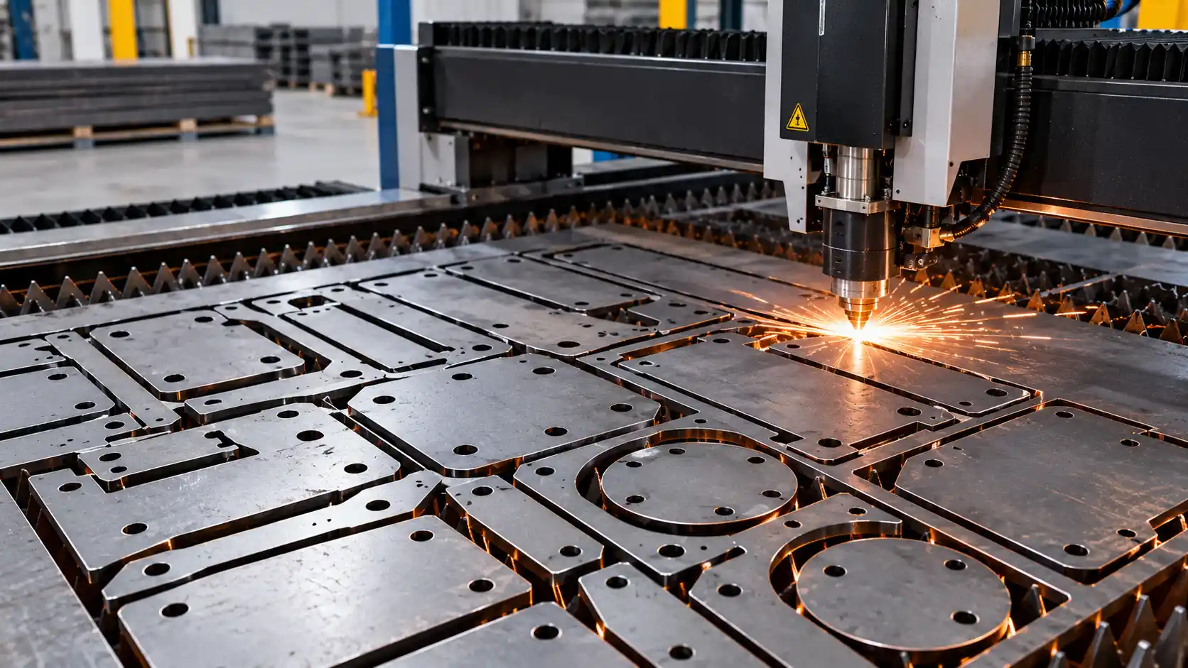
Steel plate nesting is the process of arranging component shapes on a steel plate before cutting to use the available material efficiently. A suitable layout can reduce scrap, improve material utilization and help manufacturers control production costs.
Nesting can be performed manually for simple jobs or with specialized software for complex CNC cutting operations. The software considers part geometry, plate dimensions, cutting kerf, spacing and other manufacturing constraints to generate a practical cutting layout.
Understanding how nesting works helps metal fabricators improve material planning, reduce unnecessary waste and make better use of their available steel stock.
What Is Steel Plate Nesting?
Steel plate nesting is the arrangement of multiple component shapes within a larger sheet or plate before the cutting process begins. The objective is to fit the required parts into the available material while respecting cutting limitations and engineering requirements.
For example, a manufacturer may need to cut brackets, mounting plates and machine supports from one large steel plate. Instead of positioning each component independently, the fabricator plans their placement together to minimize unused space.
A nesting layout must account for more than the outline of each component. The cutting machine needs sufficient clearance between parts, and the material must remain suitable for handling and cutting. Some components may also have restrictions on orientation, surface direction or dimensional tolerances.
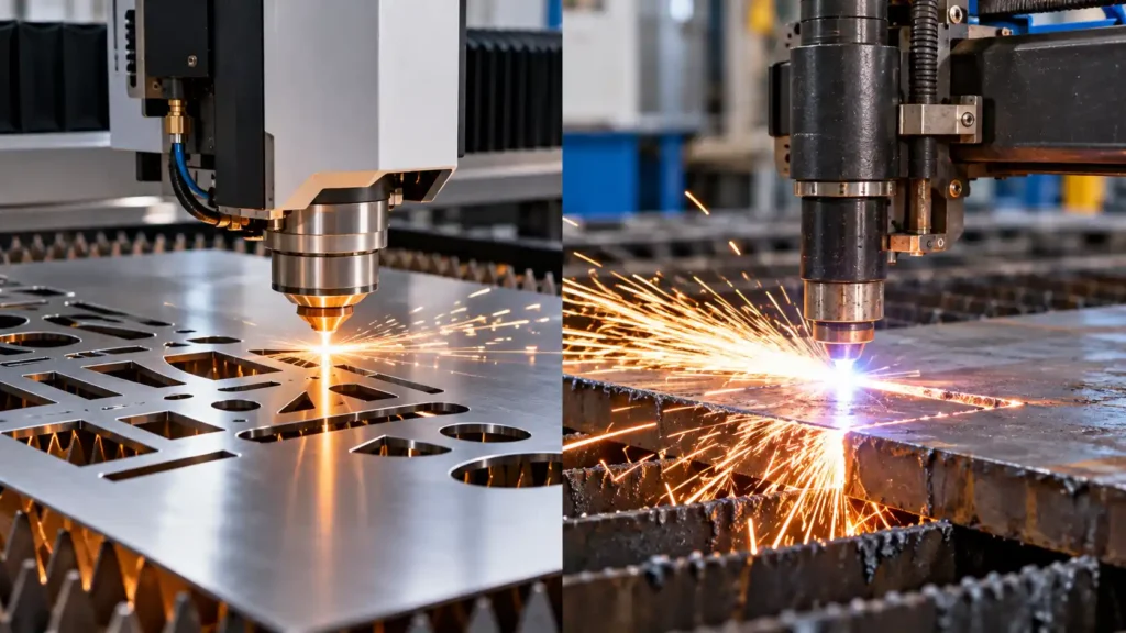
Nesting is commonly used with CNC laser cutting, plasma cutting and oxy-fuel cutting systems. Each process has different requirements, so the best layout depends on the machine, material thickness and component design.
How Does Nesting Software Arrange Parts?
Nesting software imports part drawings or geometry, then evaluates different ways to position the components on a sheet or plate. Depending on the software, it may rotate parts, group similar shapes, arrange multiple components and generate a cutting sequence.
The aim is to balance material utilization with cutting time, part quality and machine limitations.
1. Part Geometry and Plate Dimensions
The software first needs accurate information about the shapes to be cut and the dimensions of the available plate.
A plate measuring 2,000 × 1,000 mm provides a different layout opportunity from one measuring 3,000 × 1,500 mm. Likewise, a group of rectangular parts may be easier to arrange than irregular components with curves, holes or angled edges.
The nesting program checks whether the parts fit within the usable cutting area while respecting the machine’s travel limits and any required edge margins.
2. Cutting Kerf and Spacing
Cutting kerf is the width of material removed by the cutting process. A laser, plasma torch or oxy-fuel torch consumes material along the cutting path, so the layout must account for the space required between adjacent cuts.
If the spacing is too small, cuts may overlap or damage nearby parts. Insufficient clearance can also affect heat management, edge quality and part stability.
The required spacing depends on the cutting process, material thickness, geometry, machine settings and nesting strategy. Some systems support common-line cutting, where adjacent parts share a cutting line when the process and part design allow it.
3. Part Rotation and Orientation
Rotating parts can help the software find better-fitting arrangements. A rectangular bracket, for example, may fit into an unused area when rotated by 90 degrees.
However, not every component can be rotated freely. Grain direction, rolling direction, surface appearance, bending requirements or engineering specifications may restrict its orientation.
A good nesting program follows these constraints instead of maximizing material utilization at the expense of part quality.
4. Cutting Sequence
The arrangement of parts is only one part of the process. Nesting software may also help plan the cutting sequence to reduce unnecessary machine movement and manage heat buildup.
The correct sequence depends on the machine, material and component geometry. Thin parts can move or distort as surrounding material is removed, while some layouts require specific cutting order to maintain stability.
Efficient nesting therefore considers both material use and practical cutting performance.
What Is Material Utilization Percentage?
Material utilization measures the proportion of the starting plate that becomes usable finished parts. It is a useful indicator for comparing nesting layouts and estimating material waste.
The basic formula is:
Material Utilization (%) = (Total Usable Part Area ÷ Starting Plate Area) × 100
The unused portion can be estimated as:
Unused Material (%) = 100 − Material Utilization (%)
These calculations use area as a simplified measure. In actual production, the final amount of scrap also depends on cutting kerf, unusable remnants, defects, part requirements and whether leftover material can be reused.
Worked Example: Calculating Material Utilization
Suppose a fabricator has a steel plate measuring 2,000 mm × 1,000 mm.
- Plate length: 2,000 mm
- Plate width: 1,000 mm
- Total plate area: 2,000,000 mm²
- Combined area of usable parts: 1,500,000 mm²
The calculation is:
Material utilization = (1,500,000 ÷ 2,000,000) × 100
Material utilization = 75%
The estimated unused area is:
2,000,000 − 1,500,000 = 500,000 mm²
This means 75% of the plate area becomes usable parts, while 25% remains outside the finished-part area.
The example is illustrative. In a real nesting job, the actual result depends on the part shapes, kerf, spacing, edge margins and whether leftover pieces can be reused. A layout with higher area utilization may not always produce the shortest cutting time.
Common Metal Cutting Nesting Patterns
Different part shapes and production requirements call for different nesting approaches.
Rectangular Nesting
Rectangular nesting is useful when parts have straight edges and regular shapes. Components are arranged in rows or columns, often with rotations to use available space.
This method can work well for simple brackets, panels and rectangular plates.
Mixed-Part Nesting
Mixed-part nesting places different component shapes on the same plate. It can improve material use when a production order contains several part sizes.
The software must account for clearances, part orientation, cutting paths and the quantity required for each component.
Shape-Based Nesting
Irregular parts may fit together more efficiently when their contours are considered. For example, curved or angled components can sometimes be placed near the unused spaces of neighboring parts.
The result depends on the geometry and manufacturing constraints. Closely fitting shapes still need enough space for safe, reliable cutting.
Common-Line Cutting
Common-line cutting allows adjacent parts to share a cutting boundary where the geometry, process and quality requirements permit it. This can reduce duplicated cutting paths and material loss.
However, it is not suitable for every part or material. Shared edges may affect heat distribution, dimensional quality or the ability to separate components safely.
Manual vs Automatic Nesting
Fabricators can prepare layouts manually or use automatic nesting software. Both approaches have a place in metal manufacturing.
| Factor | Manual Nesting | Automatic Nesting |
|---|---|---|
| Setup | Often straightforward for simple jobs | Requires suitable software and part data |
| Best suited for | Small jobs and regular shapes | Complex layouts and repeated production |
| Layout optimization | Depends on operator experience | Evaluates multiple possible arrangements |
| Processing time | Can increase with job complexity | Can reduce layout planning time |
| Constraints | Managed manually | Can apply defined rotation, spacing and material rules |
| Cost | Lower software requirements | Software, training and integration costs |
| Repeatability | Depends on documentation and operator method | Layouts can be saved and reused |
Manual nesting can be effective when there are only a few simple parts. Automatic nesting becomes more useful when the job contains many shapes, multiple material sizes or recurring production orders.
Software results should still be reviewed by a qualified operator. Incorrect part drawings, unsuitable settings or missing constraints can create an impractical layout even when the software reports high material utilization.
Nesting for CNC Laser, Plasma and Oxy-Fuel Cutting
Nesting is used with several CNC metal-cutting technologies, but each process has distinct operating characteristics.
CNC Laser Cutting
Laser cutting is commonly used for sheet metal and precision components. Its relatively narrow kerf on suitable materials can support close nesting and detailed shapes.
The layout must still account for material thickness, heat effects, minimum feature sizes and the manufacturer’s recommended cutting parameters.
CNC Plasma Cutting
Plasma cutting is widely used for electrically conductive metals, including many steel plates. It is often selected for fabrication jobs involving thicker material and larger structural components.
Plasma kerf, torch clearance, heat input and edge quality influence the nesting layout. Appropriate spacing helps prevent cutting interference and supports reliable part separation.
Oxy-Fuel Cutting
Oxy-fuel cutting uses a fuel-gas flame and oxygen to cut suitable metals, particularly carbon steel. It is often used for heavy plate and industrial fabrication.
The cutting process may involve a wider kerf and a larger heat-affected area than some laser applications. Nesting must account for torch movement, spacing, material thickness and the risk of thermal distortion.
For manufacturers researching automated cutting equipment, CNC machines from Mekantra Technologies provide a relevant starting point for exploring CNC machinery options.
How to Reduce Steel Plate Scrap
Effective steel plate cutting optimization combines good software, accurate part data and practical production planning.
- Choose suitable plate sizes: Match stock dimensions to the parts required for the production order.
- Combine compatible jobs: Nest parts made from the same material grade and thickness when scheduling allows.
- Use rotation where permitted: Rotate components to fill unused areas without violating orientation requirements.
- Account for kerf and spacing: Apply the correct cutting parameters and clearances for the process.
- Reuse suitable remnants: Record leftover pieces that are large and defect-free enough for future jobs.
- Maintain accurate drawings: Incorrect dimensions or missing constraints can cause poor layouts and rejected parts.
- Review cutting sequences: Avoid unnecessary travel and manage heat buildup where the process requires it.
- Track material utilization: Compare layouts and actual production results to identify opportunities for improvement.
Scrap reduction should not come at the expense of safety, part quality or reliable cutting. A practical layout balances material efficiency with the requirements of the finished components.
Frequently Asked Questions
What is steel plate nesting?
Steel plate nesting is the process of arranging component shapes on a plate before cutting to use material efficiently and reduce unused space.
What is a good material utilization percentage?
There is no single target for every job. Utilization depends on part geometry, plate dimensions, cutting method, spacing and orientation restrictions. Compare layouts for similar jobs rather than relying on a universal benchmark.
How does nesting software reduce material waste?
Nesting software evaluates different part arrangements, rotations and spacing rules to find a layout that uses available material efficiently while respecting manufacturing constraints.
Can nesting be used with laser, plasma and oxy-fuel cutting?
Yes. All three processes can use nesting layouts. The layout must account for the specific process’s kerf, clearance, heat effects and cutting requirements.
Can leftover steel plate be reused?
Suitable remnants can often be stored and reused if their dimensions, material grade, thickness and condition meet the requirements of a future job. Proper identification and inventory records help make remnant reuse practical.
Conclusion
Steel plate nesting helps manufacturers arrange parts efficiently before cutting, improving material utilization and reducing unnecessary scrap. By considering plate dimensions, part geometry, kerf, spacing, orientation and cutting sequence, fabricators can develop layouts that balance material efficiency with production requirements.
Manual nesting can work well for simple jobs, while automatic nesting software can support complex and recurring CNC cutting operations. The best results come from accurate drawings, suitable cutting parameters, well-managed remnants and regular review of actual material usage.
For metal fabrication businesses, nesting is a practical way to improve material planning, control costs and make better use of steel stock.
Explore Mekantra Technologies
Explore Mekantra Technologies for information about industrial machinery and CNC equipment sourcing.

Mekantra Engineering Team
The technical voice of Mekantra. Our team consists of sourcing specialists, mechanical engineers, and logistics experts dedicated to providing transparent insights and high-performance solutions for the global manufacturing sector.
Mekantra Engineering Team
The technical voice of Mekantra. Our team consists of sourcing specialists, mechanical engineers, and logistics experts dedicated to providing transparent insights and high-performance solutions for the global manufacturing sector.