Air Brake Systems: Valve & Compressor Guide
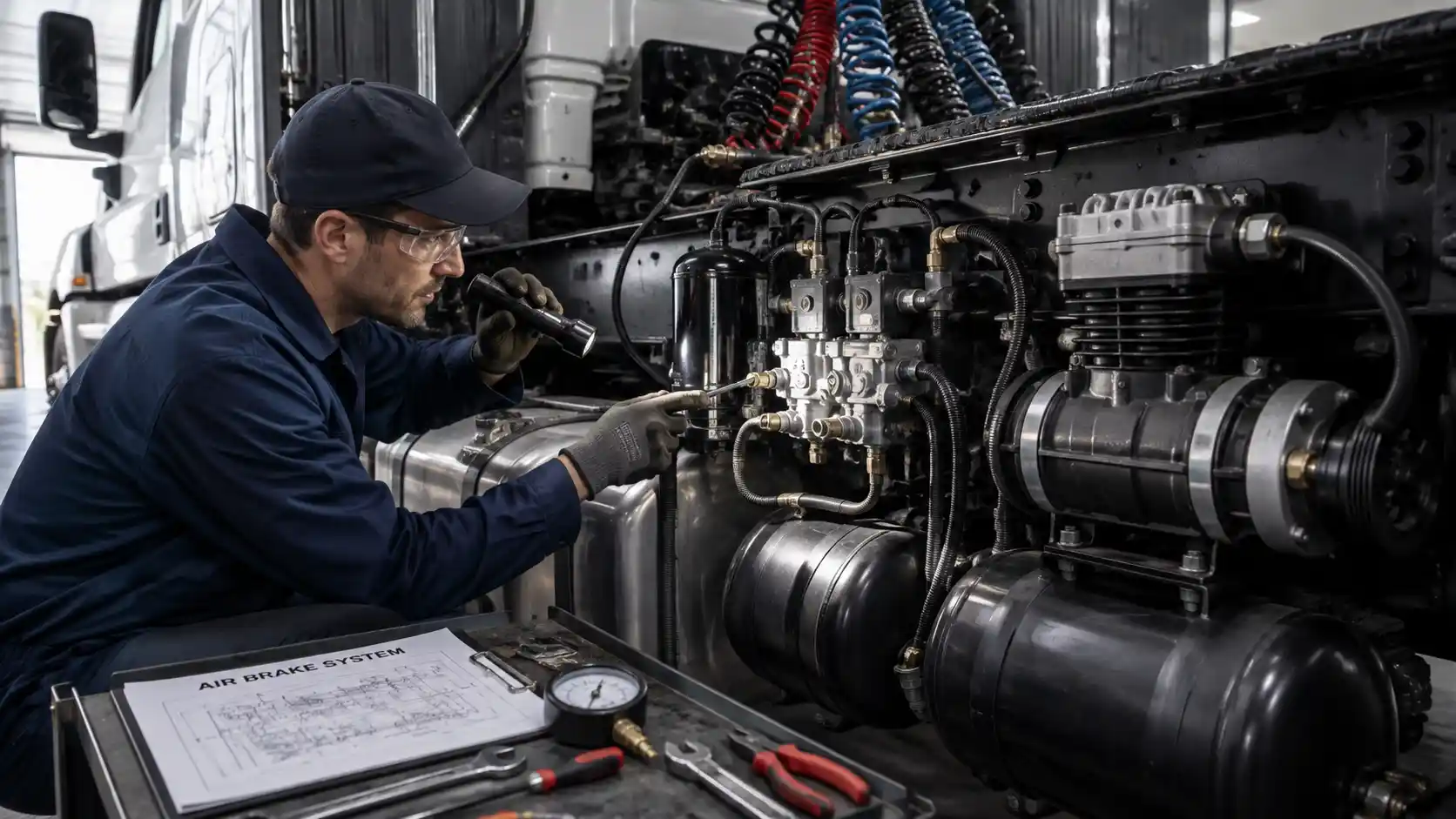
Heavy-duty air brake failure leads to costly road calls and critical FMCSA violations. This complete guide breaks down step-by-step diagnostic workflows for air compressors, governors, and valve failures. Learn how to pinpoint pressure drops, prevent oil contamination, and maintain maximum fleet uptime.
For commercial fleet operators, heavy-duty trucks, and Class 8 haulers across the United States, pneumatic safety is non-negotiable. An air brake system failure does not merely cause an annoying road call; it leads to severe Department of Transportation (DOT) Out-of-Service (OOS) violations, costly towing fees, and critical safety hazards on public highways.
At the center of every commercial air brake setup lies a dual-circuit pneumatic network powered by the air compressor and regulated by precision valves. When air pressure builds too slowly, valves leak from exhaust ports, or compressors blow oil into the air dryer, maintenance managers must quickly pinpoint the root cause.
The Heart of the Pneumatic System: Air Compressors and Governors
The engine-driven air compressor serves as the power source of the entire braking system, pumping atmospheric air into high-pressure storage reservoirs. The air governor manages this charging process by monitoring air pressure in the primary reservoir and controlling compressor loading and unloading cycles.
+---------------------------------------------------------------------------------+
|                               AIR BRAKE CHARGING CYCLE                          |
|                                                                                 |
|  [ Engine Drive ] ---> [ Air Compressor ] --------> [ Air Dryer ]              |
|                             ^                             |                     |
|                             | (Unloader Signal Line)      v                     |
|                      [ Air Governor ] <------- [ Primary Reservoir ]            |
|                     (Senses 100-125 PSI)                  |                     |
|                                                           v                     |
|                                              [ Secondary Reservoirs ]           |
+---------------------------------------------------------------------------------+
Air Governor Operation Dynamics
The governor operates on two critical set points:
- Cut-Out Pressure (120–135 PSI): When system pressure reaches the maximum operating threshold, the governor sends a pneumatic pressure signal to the compressor unloader mechanism. This opens the unloader valves in the compressor cylinder head, allowing air to bypass back into the intake without building further pressure. Simultaneously, a signal triggers the air dryer to purge stored moisture.
- Cut-In Pressure (100–105 PSI): As air is consumed during braking cycles or auxiliary usage, system pressure drops. Once pressure hits cut-in, the governor exhausts its control line signal, closing the compressor unloader valves. The compressor resumes active pumping into the reservoirs.
Step-by-Step Compressor Diagnostics
When a driver reports low air warnings or extended pressure build-up times, perform tests systematically before condemning the compressor.
Pressure Build-Up Time Test
Under Federal Motor Vehicle Safety Standards (FMVSS 121), air pressure must build from 85 PSI to 100 PSI within 25 to 40 seconds with the engine operating at maximum governed RPM (or under 2 minutes at idle).
   [ Start Engine & Set to Max Governed RPM ]
                      |
                      v
   [ Monitor Dash Pressure Gauge ]
                      |
   +------------------+------------------+
   |                                     |
   v                                     v
[ 85 -> 100 PSI in <= 40s ]           [ 85 -> 100 PSI > 40s ]
   |                                     |
   v                                     v
 PASS (System Normal)                 FAIL (Troubleshoot Flow Below)
                                         |
                                         +---> Check Clogged Air Intake Filter
                                         +---> Check Carbon Build-up in Discharge Line
                                         +---> Inspect Air Dryer Bypass
                                         +---> Check Unloader Plunger Sticking
Diagnostic Steps for Slow Pressure Build-Up:
- Inspect Air Intake and Filters: A clogged air intake line or dirty air filter starves the compressor of air, causing long charge times and pulling excessive oil past piston rings.
- Check the Discharge Line for Carbon Buildup: High operating temperatures cause oil vapors to bake onto the inner wall of the copper/braided steel discharge line. Carbon restrictions restrict airflow into the air dryer, resulting in backpressure and slow pressure recovery.
- Test the Governor Signal and Unloader Mechanism: If the governor or unloader plungers stick partially open, the compressor will continually bleed off air or fail to load completely. Disconnect the unloader sensing line at the governor. If air leaks continuously through the governor exhaust port when pressure is below cut-in, replace the governor.
Critical Valve Troubleshooting Matrix
Commercial air brake systems use directional, pressure-regulating, and quick-acting relay valves. The table below lists primary failure modes, symptoms, and field remedies:
| Component | Function | Failure Symptom | Root Cause | Corrective Action |
| Air Governor | Regulates compressor loading & unloading cycles | Compressor won’t cut-in or cut-out; safety valve pops | Internal diaphragm rupture or plugged sensing port | Adjust set screw or replace governor unit. |
| Relay Valve | Speeds up brake application & release at rear axles | Continuous air leak out of exhaust port when brakes are released | Damaged internal O-ring seal OR back-feeding spring brake chamber | Perform back-feed isolation test before replacing valve. |
| Purge Valve (Air Dryer) | Exhausts water & oil contaminants during compressor unload | Constant air blowing out air dryer purge valve during engine run | Stuck purge valve seal or failed internal heater in cold climates | Replace purge valve kit or service desiccant cartridge. |
| Foot Valve (Treadle) | Dual-circuit control valve operated by driver foot pedal | Air leaks out of exhaust port when pedal is released | Contamination on valve seat or internal spring failure | Flush air lines, clean valve body, or install rebuild kit. |
| Quick Release Valve | Quickly vents service brake chambers during brake release | Slow or dragging brake release on front steer axle | Swollen internal rubber diaphragm due to oil saturation | Replace valve diaphragm and inspect compressor for blow-by. |
| Check Valves | Prevents reverse air flow between reservoirs | Draining primary tank bleeds secondary tank simultaneously | Dirt, rust, or metal shavings trapped in valve seat | Flush lines and replace damaged single or double check valves. |
Isolating Valve Exhaust Diagnostics
A common diagnostic mistake made by technicians is replacing a leaking air valve without verifying where the leaking air originated. Because pneumatic systems interconnect through relay valves, tractor-protection circuits, and spring-brake double-check valves, air escaping from a valve’s exhaust port often originates from a completely different component further down the line.
                 [ AIR LEAK DETECTED AT RELAY VALVE EXHAUST ]
                                      |
                                      v
              [ Disconnect Service Delivery Lines From Relay Valve ]
                                      |
                 +--------------------+--------------------+
                 |                                         |
                 v                                         v
   [ Air Continues to Flow From Valve ]     [ Air Blows Back From Disconnected Hose ]
                 |                                         |
                 v                                         v
         REPLACE RELAY VALVE                  FAULT IS DOWNSTREAM / BACK-FEEDING
     (Internal Valve Seal Damaged)            (Check Spring Brake Chamber Diaphragm
                                               or Double Check Valve)
The Spring Brake Chamber Back-Feed Test
If a dual-diaphragm spring brake chamber suffers an internal failure (a ruptured center seal), high-pressure air from the parking brake circuit leaks directly into the service brake chamber. This back-fed air travels backward up the service delivery hose and exhausts out of the service brake relay valve.
Replacing the relay valve in this scenario will not fix the problem.
How to Isolate a Back-Feeding Chamber:
- Block the vehicle wheels and release the parking brakes (push yellow dash knob IN).
- Identify the valve leaking air out of its exhaust port.
- Disconnect the delivery air line leading to the spring brake chamber service port.
- Check for air blowing backward out of the disconnected hose. If air streams back from the hose, replace the faulty piggyback spring brake chamber diaphragm, not the relay valve.
Moisture and Oil Contamination
Moisture and oil are two of the greatest causes of premature air brake component failure. Atmospheric air contains humidity that condenses into liquid water inside cold air tanks. Additionally, all reciprocating compressors pass a minor amount of aerosolized oil past their piston rings during operation.
+-----------------------------------------------------------------------------------+
|                        CONTAMINATION IMPACT ON AIR BRAKE SYSTEM                   |
|                                                                                   |
|  [ Excess Engine Oil Blow-by ] + [ High Intake Humidity / Condensation ]          |
|                                         |                                         |
|                                         v                                         |
|                 [ Saturation of Air Dryer Desiccant Cartridge ]                   |
|                                         |                                         |
|                                         v                                         |
|             [ Carbon Oil Sludge Enters Air Distribution System ]                  |
|                                         |                                         |
|      +----------------------------------+----------------------------------+      |
|      |                                                                     |      |
|      v                                                                     v      |
| [ Rubber O-Rings & Diaphragms Swell ]             [ Sub-Zero Moisture Freezing ]  |
|      |                                                                     |      |
|      v                                                                     v      |
| [ Valves Stick / Exhaust Leakage ]                [ Air Line & Valve Ice Blockage]|
+-----------------------------------------------------------------------------------+
Preventive Actions for Clean System Air:
- Daily Reservoir Draining: Manual wet-tank drain valves must be pulled daily to evaluate system contamination levels. Finding a few drops of water is normal, but finding several ounces of liquid water or milky sludge indicates an air dryer failure.
- Annual Desiccant Replacement: Replace the air dryer desiccant cartridge annually (or every 100,000 miles for long-haul operations).
- Use Thread Sealant Sparingly: When installing air fittings into replacement valve ports, use approved pipe thread sealant sparingly. Liquid thread sealant or excess thread tape that enters the internal valve chamber will jam rubber seals and cause valve lockups.
Fleet PM & Inspection Checklist for Air Brake Compliance
To maintain DOT/FMCSA safety compliance and lower total cost of ownership (TCO), incorporate these diagnostic benchmarks into your standard fleet maintenance schedule:
1. Static Air Loss Leakage Test
- Charge the air system to cut-out pressure (approx. 120–135 PSI). Turn off the engine.
- Release parking brakes (push yellow/red knobs in).
- Observe the dash pressure gauge for 1 minute. Max allowable pressure drop:
- Straight Truck / Bus: 2 PSI per minute.
- Tractor-Trailer Combination: 3 PSI per minute.
2. Applied Air Loss Leakage Test
- Hold the foot brake pedal firmly in the fully applied position for 1 minute. Max allowable pressure drop:
- Straight Truck / Bus: 3 PSI per minute.
- Tractor-Trailer Combination: 4 PSI per minute.
- Action Required: If leakage exceeds limits, apply a soap-and-water solution to all air lines, fittings, brake chambers, and valve exhaust ports to pinpoint escaping air bubbles.
3. Low Pressure Warning Signal Test
- Turn the ignition key to ON with the engine off.
- Fan the foot brake pedal repeatedly to reduce air pressure.
- Verify that the low-pressure warning light and buzzer activate at or above 60 PSI.
Fleet reliability depends not only on fast diagnostics, but also on sourcing high-grade pneumatic components built for heavy-duty demand. Whether you are replacing worn air governors, purge valves, or complete compressor assemblies, stocking dependable heavy-duty commercial vehicle parts ensures your trucks meet stringent DOT standards and remain active on the road.
OEM vs. Aftermarket Air Brake Components: Fleet Reliability Perspective
When repairing heavy-duty air brake systems, fleet operators often weigh the upfront cost of original equipment manufacturer (OEM) parts against aftermarket alternatives.
+----------------------------------------------------------------------------------+
|                  OEM VS. AFTERMARKET PNEUMATIC COMPONENT COMPARISON              |
|                                                                                  |
|  CRITERIA            OEM (Bendix/Haldex/WABCO)       AFTERMARKET ALTERNATIVES    |
|  ------------------  --------------------------      --------------------------  |
|  Casting Tolerances  Precision Machined              Variable Quality Control    |
|  Extreme Temp Diaph  Certified Vulcanized Synthetic  Standard Nitrile Rubber     |
|  Warranty Coverage   Nationwide Support              Limited Distributor Basis   |
|  DOT Compliance      Guaranteed FMVSS 121            Must Verify Standards       |
+----------------------------------------------------------------------------------+
While high-quality aftermarket valves can offer cost savings, critical control components—such as air governors, main foot valves, and tractor protection valves—should meet exact OEM tolerance standards. Inferior internal valve springs or rubber compounds can deteriorate rapidly under high temperatures or synthetic oil carryover, leading to premature valve stickiness and unexpected road failures.
Maintaining heavy-duty commercial air brakes requires a clear, methodical diagnostic approach:
- Never assume a leaking valve exhaust port means the valve itself is broken. Always test for downstream back-feeding before swapping parts.
- Monitor air build-up times closely. Slow build times stem from restricted compressor intake filters, clogged discharge lines, or sticking unloader mechanisms.
- Control contamination at the source. Maintain air dryer desiccant cartridges and drain wet tanks regularly to prevent oil sludge and moisture from degrading valve seals.
By implementing these diagnostic routines and choosing high-reliability parts, commercial fleets can minimize costly downtime, protect drivers, and easily pass roadside DOT inspections.

Mekantra Engineering Team
The technical voice of Mekantra. Our team consists of sourcing specialists, mechanical engineers, and logistics experts dedicated to providing transparent insights and high-performance solutions for the global manufacturing sector.
Mekantra Engineering Team
The technical voice of Mekantra. Our team consists of sourcing specialists, mechanical engineers, and logistics experts dedicated to providing transparent insights and high-performance solutions for the global manufacturing sector.