CNC Machine Tolerance: What It Is & Why It Matters
In the world of modern manufacturing, perfection is an illusion. No matter how advanced the technology gets or how skilled the machinist is, producing a metal or plastic component to the exact, mathematically perfect dimension every single time is physically impossible. There will always be microscopic variations. This is exactly where CNC machine tolerance comes into play.
Whether you are producing high-performance aerospace engine components, medical devices, or simple mounting brackets, understanding machining tolerances is the key to ensuring parts fit together correctly without unnecessarily driving up your production costs.
At Mekantra Technologies, we know that choosing the right equipment whether you are looking for a reliable CNC lathe machine or a heavy-duty metal CNC machine requires a deep understanding of what these machines can physically achieve.
What is CNC Machining Tolerance?
In the realm of CNC (Computer Numerical Control) machining, tolerance is defined as the acceptable limit of variation in a physical dimension. It is the allowable “breathing room” for a specific measurement.
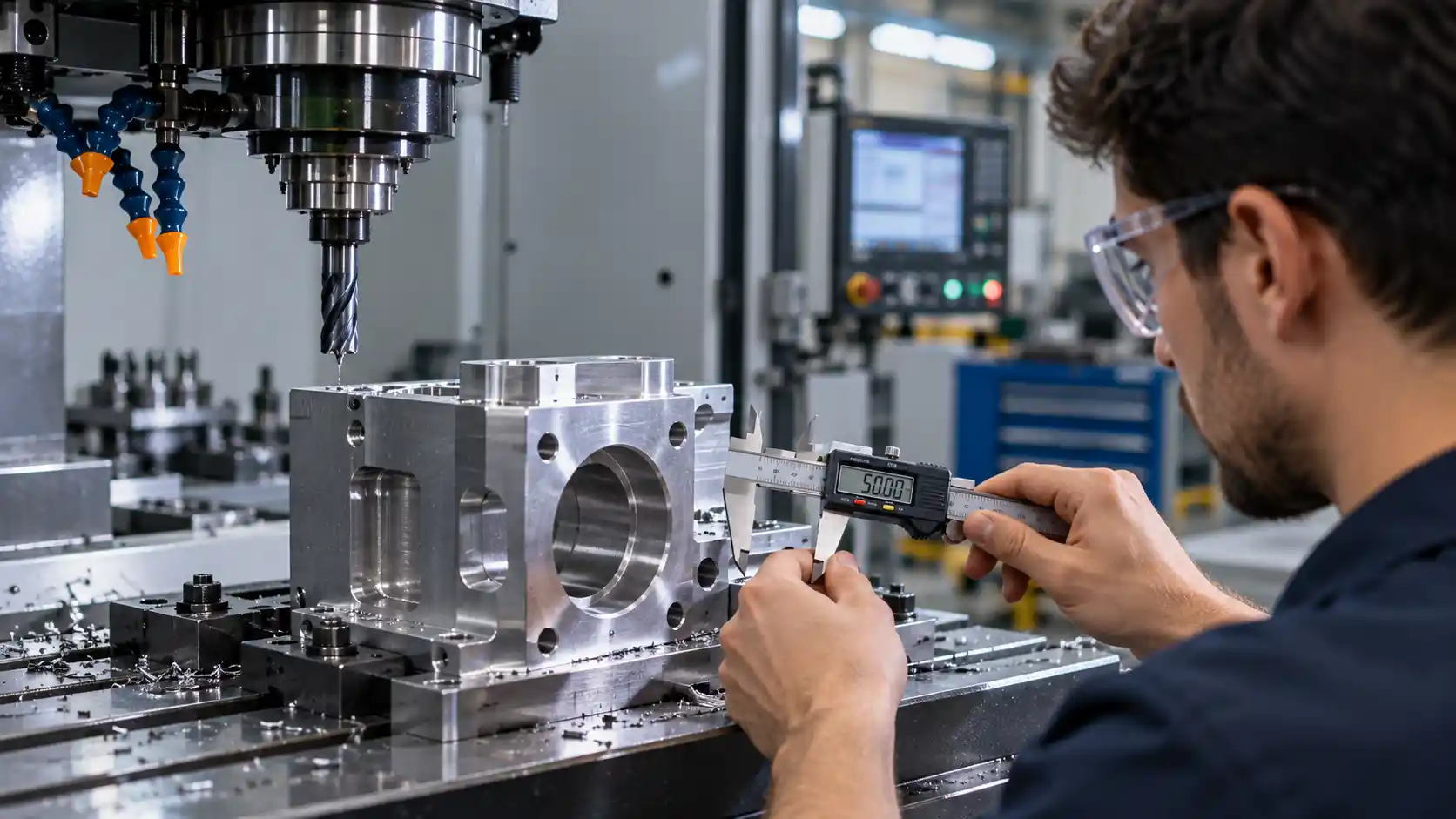
Since a CNC machine cannot hit an exact, infinite dimension (like exactly 50.000000 mm) on every single part due to real-world physical variables, mechanical engineers and designers assign a tolerance limit. This tells the machinist and the quality control inspector how much room for error is acceptable while keeping the final part fully functional and safe for use.
Why ± (Plus/Minus) Values Are Used
When looking at an engineering drawing or blueprint, you will almost always see tolerances written with a “±” (plus or minus) symbol next to the nominal (target) dimension. This symbol indicates the upper and lower limits of acceptable size.
- A Practical Example: If a blueprint calls for a stainless steel shaft to be 50mm ± 0.1mm, it means the part will be considered acceptable and functional as long as the final physical measurement falls anywhere between 49.9mm (the lower limit) and 50.1mm (the upper limit).
If the machined shaft measures 50.05mm, it passes inspection. If it measures 50.15mm, it is rejected and likely scrapped. The ± value gives machine operators a clear, measurable window to aim for, ensuring high CNC dimensional accuracy without demanding scientifically impossible perfection.
Tolerance vs. Accuracy vs. Precision
In everyday conversation, these three terms are often used interchangeably. However, in the strict world of precision CNC machining, they have completely different meanings. Understanding the distinction is vital for evaluating CNC machine accuracy and setting realistic production goals.
1. CNC Accuracy (Hitting the Target)
CNC accuracy refers to how close a machined measurement is to the true, intended design value. If you program the machine to cut a block of aluminum to exactly 100mm, and the machine cuts it to 100.01mm, it is highly accurate. Think of accuracy as hitting the bullseye on a dartboard.
2. CNC Precision (Repeatability)
CNC precision refers strictly to repeatability. It is the machine’s mechanical ability to hit the exact same physical spot, time after time, part after part. If you machine 1,000 blocks and they all measure exactly 100.08mm, the machine is incredibly precise (because the results are identical across all 1,000 parts), even if it is slightly inaccurate (because it missed the 100mm target by 0.08mm). Think of precision as throwing five darts that all land in a tight cluster in the exact same spot, even if that spot is in the corner of the dartboard outside the bullseye.
3. Machining Tolerance (The Allowed Target Size)
Tolerance is the size of the bullseye itself. It is the boundary defined by the designer, not the machine. You can have a highly precise and accurate metal CNC machine, but if the engineering tolerance is set too tight for the machine’s physical capabilities, the parts will still fail inspection.
| Term | Engineering Definition | Dartboard Analogy |
|---|---|---|
| Accuracy | The closeness of a measurement to the exact intended target value. | Darts land very close to the center bullseye. |
| Precision | The ability to reproduce the exact same measurement repeatedly. | Darts all land in a very tight cluster in the same spot. |
| Tolerance | The mathematically acceptable range of deviation from the true value. | The physical size of the bullseye area you are allowed to hit. |
Tight vs. Loose Tolerances
When defining machining tolerances for a new product, engineers must choose between “tight” and “loose” specifications based strictly on the part’s final application. Applying the wrong type of tolerance can ruin a project’s budget.
Tight Tolerances
Tight tolerances leave very little room for mechanical error. Measurements are often restricted to ± 0.001 inches (0.025 mm) or even smaller. These are required for parts that must fit seamlessly and dynamically with other components. Examples include aerospace turbine blades, medical joint implants, precision automotive pistons, and complex gear assemblies. Achieving tight tolerances requires top-tier CNC machine accuracy, specialized tooling, slower machining speeds, and frequent mid-process measurement.
Loose Tolerances
Loose tolerances offer a significantly larger margin of error, often around ± 0.030 inches (0.75 mm) or more. These are used for non-critical features where exact sizing doesn’t impact function. Examples include the outer casing of a machine, a basic mounting bracket, or clearance holes drilled simply for passing electrical cables through. Loose tolerances are vastly faster and cheaper to manufacture because they do not require constant machine adjustments or expensive inspection processes.
6 Critical Factors Affecting CNC Machining Tolerance
Achieving optimal CNC dimensional accuracy is not just about programming the CAM (Computer-Aided Manufacturing) software correctly. Machining is a violent physical process influenced by real-world variables. Here are the primary factors that dictate your machine’s ability to hold a tolerance.
1. Machine Condition and Rigidity
The physical health and structural rigidity of your CNC machine dictate its baseline performance. Older machines with worn-out linear guides, mechanical backlash in the ball screws, or a lack of structural mass will experience microscopic vibrations (known as chatter) during cutting. These vibrations cause the cutting tool to bounce and deflect, instantly ruining the tolerance. High-quality machines, like those provided by Mekantra Technologies, are built with heavy cast-iron frames designed to absorb vibration and maintain strict accuracy under heavy loads.
2. Tool Wear and Tool Deflection
Cutting tools are subjected to immense friction and mechanical stress. Over time, the razor-sharp edge of a carbide endmill or drill bit becomes dull. A dull tool does not slice through metal cleanly; instead, it rubs and pushes against the material. This pushing causes “tool deflection”—meaning the tool physically bends at a microscopic level. If a long, thin endmill bends by 0.05mm during a cut, your final machined feature will be off by 0.05mm.
3. Material Behavior and Machinability
Different materials react very differently to being cut:
- Soft Plastics: Materials like Nylon, Delrin, or Teflon can warp, melt, or flex away from the cutting tool. They release internal stresses when cut, making tight tolerances difficult to hold.
- Hard Metals: Titanium, Inconel, and hardened tool steel cause rapid tool wear and generate massive amounts of heat, requiring constant tool changes to maintain precision.
- Aluminum: Generally very stable and easy to machine, making it highly suitable for holding tight tolerances in precision CNC machining.
4. Temperature and Thermal Expansion
Temperature is the invisible enemy of CNC accuracy. The laws of physics dictate that when metals get hot, they expand. As a CNC machine runs, the friction of cutting creates intense heat. If an aluminum part heats up by 40 degrees during machining, it will physically expand. If the machinist cuts it to the exact dimension while it is hot, the part will shrink once it cools down to room temperature, causing it to fall completely out of tolerance. Utilizing climate-controlled workshops and high-pressure flood coolant systems are essential for managing thermal expansion.
5. Cutting Parameters (Speeds and Feeds)
The spindle speed (RPM), feed rate (how fast the tool moves across the part), and depth of cut heavily influence tolerance. Taking massive, heavy cuts to save time will generate excessive heat and vibration. Achieving tight tolerances usually requires a two-step process: taking a fast “roughing” pass to remove the bulk of the material, followed by a slow, gentle “finishing” pass that takes off only a hair of material to hit the exact final dimension.
6. Metrology and Measurement Equipment
There is an old engineering saying: You cannot manufacture what you cannot measure. If a blueprint calls for a tight tolerance of ± 0.005mm, a standard set of hand calipers is completely useless. You must have Coordinate Measuring Machines (CMMs), laser scanners, and digital micrometers that are routinely calibrated to verify the dimensions accurately.
Why Tighter Tolerance Increases Complexity (and Cost)
One of the biggest mistakes novice designers make is slapping a universally tight tolerance on every single dimension of a part. While it might seem like demanding perfection guarantees a better product, it actually causes manufacturing costs to skyrocket unnecessarily.
Here is exactly why tighter tolerances increase manufacturing complexity and cost:
- Slower Cycle Times: To hold a tight tolerance, operators must slow down the feed rates and take multiple, shallow finishing passes. A part that could take 10 minutes to rough out might take 40 minutes to finish precisely.
- Higher Scrap Rates: When the acceptable margin of error is microscopic, the statistical chances of the machine slightly missing the mark increase. More rejected parts mean wasted raw material and lost time.
- Expensive Tooling: You cannot use cheap, standard cutting tools for aerospace-level precision. High-quality, specially coated solid carbide tools are required, and they must be swapped out frequently before they even show visible signs of wear.
- Advanced Setup and Fixturing: Holding a part perfectly still to avoid vibration requires custom-made fixtures and soft jaws, which adds significant engineering and setup costs prior to actually cutting the first part.
- Extensive Inspection Time: Measuring a part with loose tolerances takes a worker a few seconds. Verifying a complex part with microscopic tolerances requires programming a CMM machine and meticulously logging data, adding hours to the overall production process.
Cost vs. Tolerance Impact Chart
| Tolerance Range (mm) | Difficulty Level | Manufacturing Cost Impact | Best Application Use Case |
|---|---|---|---|
| ± 0.500 | Very Easy | Low | Outer casings, non-fitting edges, weight-reduction pockets. |
| ± 0.125 | Standard | Moderate | General assembly parts, simple brackets, standard enclosures. |
| ± 0.025 | Hard | High (2x – 3x standard) | Press-fits, dowel pins, engine components, sliding tracks. |
| ± 0.005 | Extreme | Very High (5x+ standard) | Aerospace parts, precision optics, complex medical implants. |
Real-World CNC Tolerance Examples and Standards
To standardize manufacturing across the globe and prevent confusion between designers and machine shops, engineers rely on international standard guidelines. The most common standard for general machining tolerances globally is ISO 2768.
This standard provides a baseline for what a CNC machine should reasonably be able to achieve without requiring special instructions or setups. If an engineer does not specify a specific ± tolerance on a blueprint dimension, the machinist will automatically default to the standard ISO 2768 tolerances based on the size of the cut.
Simplified ISO 2768 General Tolerance Table (Linear Dimensions)
The values below represent the allowable ± deviation in millimeters based on the overall length of the machined cut.
| Nominal Length of Cut (mm) | Fine (f) | Medium (m) | Coarse (c) |
|---|---|---|---|
| 0.5 up to 3 | ± 0.05 | ± 0.10 | ± 0.20 |
| Over 3 up to 6 | ± 0.05 | ± 0.10 | ± 0.30 |
| Over 6 up to 30 | ± 0.10 | ± 0.20 | ± 0.50 |
| Over 30 up to 120 | ± 0.15 | ± 0.30 | ± 0.80 |
| Over 120 up to 400 | ± 0.20 | ± 0.50 | ± 1.20 |
A Practical Tolerance Example in Action
Imagine you are tasked with manufacturing a stainless steel drive shaft for an industrial gearbox.
- Loose Tolerance Application: The overall length of the shaft might have a loose tolerance of ± 0.50mm. Why? Because the ends of the shaft simply sit inside a hollow casing where a half-millimeter of extra length won’t hit anything or affect the machine’s operation.
- Tight Tolerance Application: However, the diameter of that exact same shaft, specifically where it must slide perfectly into a steel ball bearing, will require an incredibly tight tolerance of ± 0.01mm. If the diameter is too small, the shaft will rattle inside the bearing and destroy the motor. If it is too large, it won’t fit into the bearing at all.
By intelligently mixing loose and tight tolerances on the exact same part, manufacturers save immense amounts of time and money while ensuring the final product functions flawlessly.
Conclusion: Balancing Precision and Practicality
Understanding CNC machine tolerance is the critical bridge between a theoretical CAD design and a physical, working product. While modern manufacturing equipment offers incredible CNC accuracy and CNC precision, pushing these machines to their absolute physical limits comes with significantly higher costs, longer production times, and increased operational complexity.
The secret to highly successful manufacturing is not demanding perfect dimensions everywhere, but applying the correct machining tolerances only where they truly matter for the part’s function. By controlling machine condition, understanding material behavior, and managing thermal variables, modern machine shops can reliably achieve exceptional CNC dimensional accuracy.
Are you looking to upgrade your manufacturing floor’s capabilities? Whether you need a high-precision CNC lathe machine capable of holding microscopic tolerances or a robust metal CNC machine designed for rapid, accurate production, having the right equipment is step one.
Visit Mekantra Technologies today to explore our comprehensive catalog of state-of-the-art precision machinery and find the perfect solution to take your manufacturing quality to the next level.

Mekantra Engineering Team
The technical voice of Mekantra. Our team consists of sourcing specialists, mechanical engineers, and logistics experts dedicated to providing transparent insights and high-performance solutions for the global manufacturing sector.
Mekantra Engineering Team
The technical voice of Mekantra. Our team consists of sourcing specialists, mechanical engineers, and logistics experts dedicated to providing transparent insights and high-performance solutions for the global manufacturing sector.