CNC Workholding Methods: Vise, Chuck or Fixture?
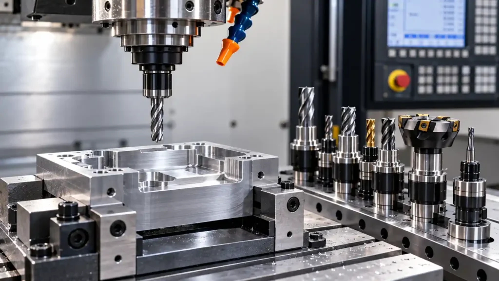
Every CNC machining operation depends on more than the cutting tool and machine settings. The workpiece must also remain securely positioned while the tool removes material. If the part moves, vibrates or becomes distorted during machining, the finished component may fail to meet its dimensional requirements.
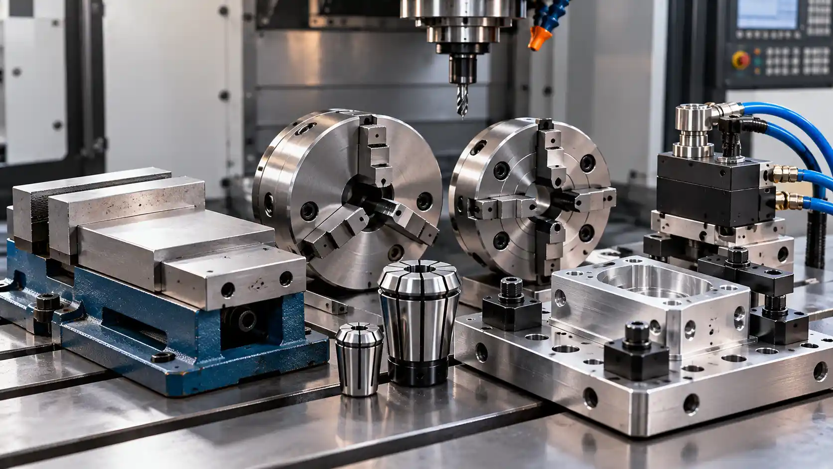
CNC workholding methods describe the techniques and devices used to secure and position workpieces during machining. Common options include machine vises, lathe chucks, collets and custom fixtures. Each method offers different advantages depending on the part’s shape, material, machining operations and production volume.
For example, a rectangular steel block may fit securely in a machine vise, while a cylindrical shaft is often held in a chuck or collet. A component with an unusual shape or multiple machining requirements may need a custom fixture.
Understanding these differences helps machinists select suitable equipment, reduce setup time and produce consistent parts.
What Is CNC Workholding?
CNC workholding is the process of locating, supporting and securing a workpiece so it remains in the correct position throughout a machining operation.
Workholding devices connect the workpiece to the machine table, spindle or another suitable mounting point. They must resist the forces generated during cutting without allowing unwanted movement.
A complete workholding setup usually performs three functions:
- Locating: Establishing the workpiece’s correct position and orientation.
- Supporting: Preventing excessive movement, bending or vibration.
- Clamping: Applying sufficient force to keep the workpiece secure during machining.
These functions work together. A strong clamp cannot compensate for poor positioning, and accurate positioning is not enough if the workpiece can move under cutting forces.
Workholding requirements also change between operations. A part may be held one way during rough machining and require a different setup for finishing or machining its opposite side.
Common CNC Workholding Methods
Different workholding devices are designed for different component shapes and machining requirements. The following options are widely used in milling, turning and other CNC operations.
1. CNC Machine Vise
A CNC machine vise holds a workpiece between two jaws. It is commonly mounted on the table of a CNC milling machine or machining center.
One jaw generally remains fixed while the other moves to clamp the part. Depending on the vise design, the workpiece may be positioned against parallels, locating stops or other supporting components.
Best suited for:
- Rectangular metal blocks.
- Flat plates and brackets.
- Components with suitable parallel surfaces.
- General milling and drilling operations.
A machine vise is useful because it is relatively straightforward to operate and can support repeatable setups when correctly aligned.
However, a vise may not be appropriate for irregular parts, thin-walled components or workpieces that cannot provide stable clamping surfaces. Excessive force can also distort softer materials or thin sections.
Using suitable jaws, supports and stops can improve stability and help reduce positioning errors.
2. Three-Jaw CNC Lathe Chuck
A three-jaw chuck is commonly used on CNC lathes to hold cylindrical or approximately round workpieces. Its jaws generally move together, helping center the workpiece around the spindle axis.
This makes it useful for turning operations where concentricity and repeatable positioning are important.
Best suited for:
- Round bars.
- Cylindrical shafts.
- Discs and rings.
- Components requiring turning, facing or boring.
The main advantage of a three-jaw chuck is convenient clamping. Operators can usually secure standard round stock quickly without adjusting each jaw independently.
However, a standard three-jaw chuck may be less suitable for irregular shapes or applications requiring precise independent adjustment. Its gripping performance also depends on the jaw condition, workpiece material, clamping force and spindle speed.
The workpiece must be secured according to the chuck manufacturer’s specifications, especially during high-speed turning.
3. Four-Jaw Chuck
A four-jaw chuck can provide independent adjustment of its jaws, allowing the operator to position round, square or irregular workpieces.
This flexibility makes it useful when the workpiece cannot be centered automatically or when its position must be adjusted carefully.
Best suited for:
- Square or rectangular components.
- Irregularly shaped parts.
- Eccentric turning operations.
- Workpieces requiring individual jaw adjustment.
A four-jaw chuck can offer greater positioning flexibility than a standard self-centering three-jaw chuck. However, setting up the workpiece may take longer because the jaws often require individual adjustment.
Operators must verify the workpiece position and secure clamping before machining. Incorrect adjustment can cause excessive runout or unsafe operation.
4. Collets
A collet is a precision clamping device that grips a workpiece around its circumference. Collets are commonly used in turning and may also be used in compatible milling systems and specialized machining equipment.
They are particularly useful for holding small or medium-sized cylindrical stock, depending on the collet system and machine.
Best suited for:
- Small-diameter shafts.
- Repeated machining of bar stock.
- Components requiring consistent positioning.
- Production jobs involving multiple similar parts.
Collets can provide good concentricity and quick loading when the workpiece matches the collet’s specified size and shape.
Their limitations include a more restricted gripping range than some chuck systems and the need to select a compatible collet for the workpiece. A collet should not be used outside its specified operating range.
5. Custom CNC Fixtures
A custom fixture is designed to hold a particular component or family of components. It may include locating pins, support blocks, clamps, stops and dedicated mounting features.
Fixtures are useful when standard vises or chucks cannot provide the required access, positioning or repeatability.
Best suited for:
- Complex component geometries.
- Parts requiring machining on multiple faces.
- Repeated production runs.
- Components that need consistent positioning between operations.
- Parts that are difficult to clamp using standard equipment.
A well-designed fixture can reduce setup time and improve consistency across repeated jobs. It may also provide better access for cutting tools.
The main disadvantage is the time and cost required for design, manufacturing and testing. A custom fixture may not be economical for a one-off part, particularly when its geometry is simple.
Fixture design should account for cutting forces, tool access, workpiece deformation, chip removal and safe loading.
6. Hydraulic and Pneumatic Clamping
Hydraulic and pneumatic systems use fluid pressure or compressed air to operate clamping mechanisms.
Hydraulic systems can generate substantial clamping forces and are commonly used in industrial fixtures and production setups. Pneumatic systems can provide fast actuation and are useful where their available force meets the application requirements.
These systems can reduce manual clamping effort and support repeatable operation in automated production.
However, the clamping force must be suitable for the workpiece and cutting operation. Pressure settings, leakage, component condition and correct workpiece seating all affect reliability.
Automated clamping does not eliminate the need to verify that the workpiece is correctly positioned and securely held.
Vise vs Chuck vs Fixture: What Is the Difference?
The most suitable workholding device depends on the workpiece geometry and the machining operation.
| Factor | Machine Vise | Three-Jaw Chuck | Custom Fixture |
|---|---|---|---|
| Typical machine | CNC milling machine | CNC lathe | Milling machine, machining center or specialized system |
| Common workpiece shape | Rectangular or prismatic | Round or cylindrical | Complex or application-specific |
| Setup time | Usually short | Usually short for compatible round stock | Can be longer initially |
| Repeatability | Good with consistent positioning | Good for compatible centered parts | Can be very good when properly designed |
| Flexibility | Suitable for many standard parts | Best for compatible workpiece shapes | Often optimized for specific parts |
| Tool access | Depends on jaw height and setup | Depends on chuck and workpiece geometry | Can be designed around tool access |
| Initial cost | Generally accessible | Depends on chuck type and machine | May require additional design and manufacturing |
| Common limitation | Can obstruct tool access or distort parts | Less convenient for some irregular shapes | Higher setup and development effort |
A collet may be preferable when consistent gripping of compatible cylindrical stock is important. Hydraulic or pneumatic clamping may be appropriate when a fixture needs faster or automated operation.
No single method is ideal for every application. The correct choice balances holding strength, positioning accuracy, accessibility, cost and setup time.
How to Choose the Right Workholding Device
Selecting a workholding device starts with understanding the part and the machining process.
1. Consider Part Geometry
The shape of the workpiece is one of the first selection factors.
Rectangular parts often work well in a vise. Cylindrical components are commonly held in chucks or collets. Irregular parts may require custom fixtures or specialized jaws.
Also consider whether the component has suitable clamping surfaces. Thin walls, angled faces and delicate features may need dedicated support to prevent movement or deformation.
2. Evaluate Clamping Force
Clamping force must be sufficient to resist cutting forces without damaging the workpiece.
Too little force may allow the part to slip, vibrate or move during machining. Too much force can distort thin-walled components, damage softer materials or affect dimensional accuracy.
The required force depends on the workpiece material, contact area, cutting forces, friction and clamping arrangement.
For critical applications, clamping should be evaluated using the machine and workholding manufacturer’s guidance. Do not assume that applying more force always creates a better setup.
3. Check Workpiece Stability
The workpiece should be supported appropriately to minimize unwanted movement and vibration.
Long or slender parts may require additional support. Large components may need multiple clamping points, while thin plates may require a fixture that distributes force more evenly.
The setup should also prevent the workpiece from lifting or shifting under the expected cutting forces.
4. Consider Tool Access
A workholding device should secure the part without unnecessarily blocking the cutting tool.
High vise jaws, chuck bodies and clamps can restrict access to important surfaces. A fixture can sometimes provide better access by locating the component from specific reference points.
Before machining, check tool travel, spindle clearance, clamp positions and potential collisions.
5. Evaluate Setup Time and Repeatability
For one-off components, a standard vise or adjustable chuck may be more economical than a dedicated fixture.
For repeated production, a fixture with defined locating points can reduce setup time and help maintain consistent positioning between parts.
The total cost should include fixture development, loading time, inspection, changeovers and the number of components produced.
Common CNC Workholding Mistakes
Incorrect workholding can cause poor surface finish, dimensional errors, damaged parts and serious safety risks.
| Mistake | Potential problem | How to prevent it |
|---|---|---|
| Insufficient clamping | Workpiece movement during cutting | Verify clamping and cutting-force requirements |
| Excessive clamping force | Part deformation or surface damage | Use suitable force for the material and geometry |
| Poor positioning | Incorrect dimensions or alignment | Clean locating surfaces and verify datum positions |
| Inadequate support | Vibration or bending | Add suitable supports where needed |
| Restricted tool clearance | Collision or incomplete machining | Check tool paths and clamp positions |
| Dirty contact surfaces | Inconsistent positioning | Remove chips and debris before clamping |
| Worn jaws or fixtures | Reduced holding reliability | Inspect and maintain workholding components |
| Incorrect chuck setup | Runout or insecure workholding | Check jaw engagement, workpiece seating and manufacturer limits |
Before starting a machining cycle, verify that the workpiece is seated correctly, the clamps are secure and the tool path is clear.
For rotating equipment, ensure the chuck, jaws and workpiece are suitable for the intended speed and operating conditions. Never adjust or handle a moving chuck.
Frequently Asked Questions
What are the most common CNC workholding methods?
Common methods include machine vises, three-jaw and four-jaw chucks, collets, custom fixtures and hydraulic or pneumatic clamping systems. The choice depends on part geometry and machining requirements.
When should I use a CNC machine vise?
A machine vise is commonly used for rectangular blocks, plates and components with suitable parallel clamping surfaces. It is particularly useful for many milling and drilling operations.
What is the difference between a three-jaw and four-jaw chuck?
A standard self-centering three-jaw chuck moves its jaws together and is convenient for many round parts. A four-jaw chuck with independently adjustable jaws provides more flexibility for square or irregular workpieces.
When is a custom CNC fixture necessary?
A custom fixture may be appropriate when a part has unusual geometry, requires machining on multiple faces or must be positioned consistently during repeated production.
How does workholding affect machining accuracy?
Workholding affects positioning, rigidity and resistance to cutting forces. Poor clamping can cause movement, vibration or deformation, resulting in dimensional errors and inconsistent part quality.
Conclusion
Choosing the right workholding system helps manufacturers improve machining stability, positioning accuracy and production consistency. Machine vises are useful for many prismatic components, chucks and collets suit different types of cylindrical workpieces, and custom fixtures address specialized geometry or repeated production requirements.
The best setup provides sufficient clamping force without distorting the part, maintains tool access and supports repeatable positioning. By considering these factors before machining begins, manufacturers can reduce setup problems and produce more reliable components. Businesses researching CNC equipment and manufacturing solutions can explore the industrial machinery information available at Mekantra Technologies to learn more about equipment relevant to their production needs.

Mekantra Engineering Team
The technical voice of Mekantra. Our team consists of sourcing specialists, mechanical engineers, and logistics experts dedicated to providing transparent insights and high-performance solutions for the global manufacturing sector.
Mekantra Engineering Team
The technical voice of Mekantra. Our team consists of sourcing specialists, mechanical engineers, and logistics experts dedicated to providing transparent insights and high-performance solutions for the global manufacturing sector.