
Dust Collector Airflow: How CFM Is Measured & Calculated
Summary:
“Dust collector airflow is the volume of air your system moves each minute, measured in CFM. This guide explains how to calculate it, measure it and keep it in the right range.”
A dust collector can look healthy from the outside and still fail at its job. The motor runs and the filters are clean, yet dust escapes from hoods and settles inside ducts. In most cases the cause is dust collector airflow: the system is not moving the right amount of air at the right speed.
What Is Airflow in a Dust Collection System?
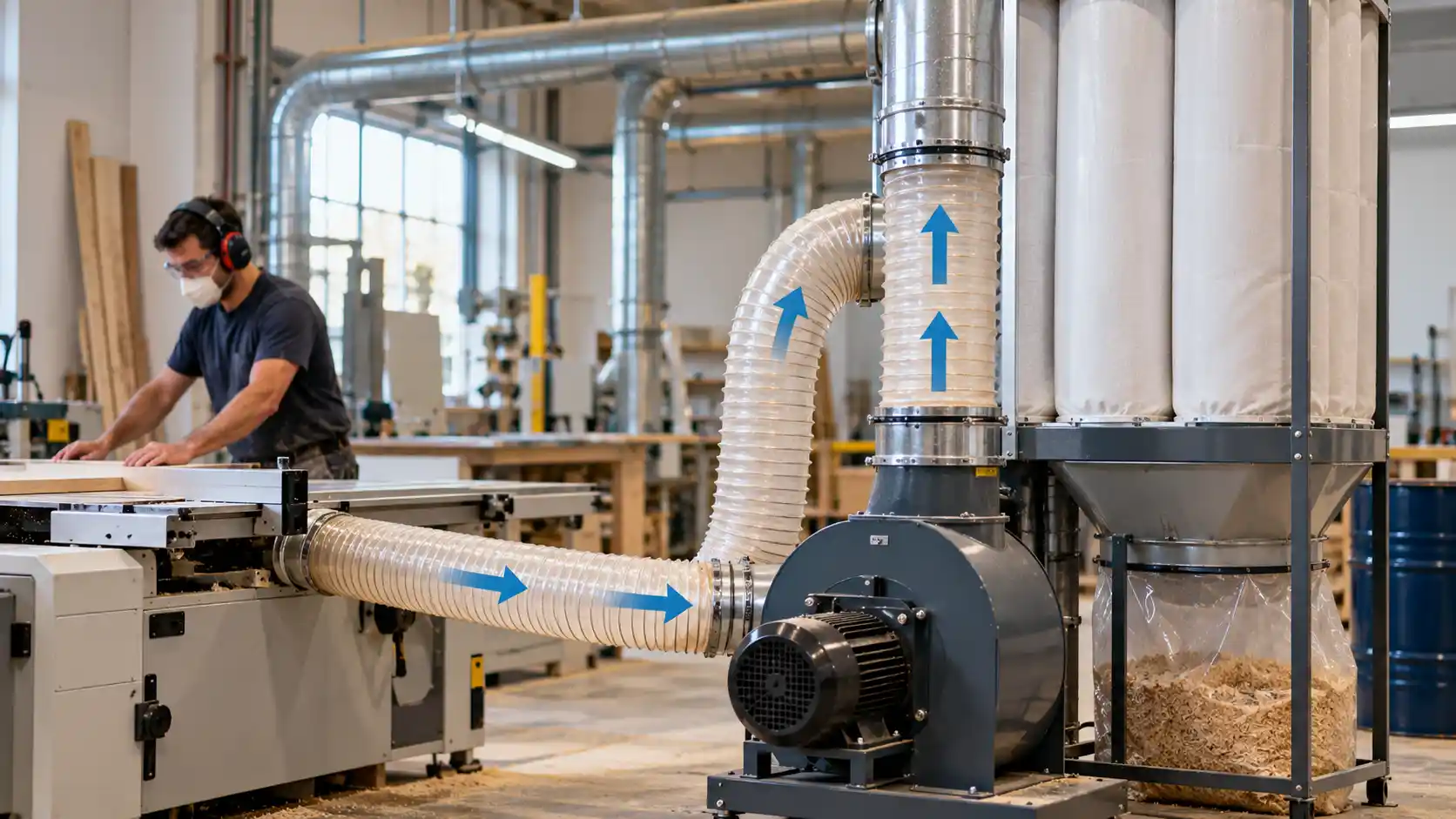
Airflow is the movement of air through hoods, ducts, filters and the fan. Its job is to pull dust-laden air away from the source, carry the particles through the ductwork, and deliver them to the collector, where the filter separates dust from air.
Airflow is described by two linked values:
- Air volume: how much air moves in a given time.
- Air velocity: how fast that air travels.
Both must be right. A system with enough volume but low velocity can still drop dust inside the duct.
What Does CFM Mean?
CFM stands for cubic feet per minute. It is the standard unit for dust collector air volume in North America and in many industrial specifications worldwide. In metric units, airflow is shown as cubic metres per hour (m³/h). One CFM equals 1.699 m³/h.
When a vendor lists a dust collector CFM rating, it normally means the volume the fan can deliver at a stated static pressure. A fan rated at 3,000 CFM in free air will deliver far less once it pushes through ducts and filters. Always read the CFM together with its pressure value.
Air Velocity vs Air Volume
These two terms are often mixed up, so keep them separate.
| Term | Unit | What it tells you | Where it matters |
| Air volume | CFM or m³/h | How much air the system moves | Fan selection, collector sizing |
| Air velocity | FPM (feet per minute) or m/s | How fast air moves at a point | Duct sizing, hood capture, dust transport |
The link between them is simple:
CFM = Duct\ area\ (ft^2) \times Velocity\ (FPM)
If the duct gets smaller and the volume stays the same, velocity rises. If the duct gets larger, velocity falls and heavy particles may settle.
Duct Diameter and Transport Velocity
Duct diameter sets the velocity for a given airflow. To keep dust moving, the air must travel faster than the speed at which particles fall out of suspension. This is called transport velocity (or conveying velocity). Typical design ranges from industrial ventilation practice are shown below. Confirm them against your own dust type and applicable standards.
| Material being conveyed | Typical duct velocity (FPM) | Approx. m/s |
| Gases and vapours | 1,000 to 2,000 | 5 to 10 |
| Fumes | 2,000 to 2,500 | 10 to 13 |
| Fine, light dry dust | 2,500 to 3,000 | 13 to 15 |
| Average industrial dust | 3,000 to 4,000 | 15 to 20 |
| Heavy or damp dust | 3,500 to 4,500+ | 18 to 23+ |
Choose the duct diameter after you know the required CFM and the target velocity, not before. The table below shows the CFM a round duct carries at 4,000 FPM.
| Duct diameter (in) | Area (ft²) | CFM at 4,000 FPM |
| 3 | 0.049 | 196 |
| 4 | 0.087 | 349 |
| 5 | 0.136 | 545 |
| 6 | 0.196 | 785 |
| 8 | 0.349 | 1,396 |
| 10 | 0.545 | 2,182 |
| 12 | 0.785 | 3,142 |
Area of a round duct in ft² = π × (diameter in inches)² ÷ 576.
Capture Velocity at the Hood
Capture velocity is the air speed needed at the dust source to pull particles into the hood. It differs from duct velocity. It depends on how the dust is released and how much room air movement is present.
| Dust release condition | Example | Capture velocity (FPM) |
| Released with no motion into still air | Tank evaporation, degreasing | 50 to 100 |
| Low speed into moderately still air | Spray booths, welding, container filling | 100 to 200 |
| Active release into fast air movement | Grinding, crushing, conveyor transfer | 200 to 500 |
| Very high speed release into rapid air | Abrasive blasting, heavy grinding | 500 to 2,000 |
For a simple open hood, a common estimate for hood airflow is:
Here Q is airflow (CFM), V is capture velocity (FPM), X is the distance from the hood face to the source (ft), and A is the hood face area (ft²). Because X is squared, a small increase in distance raises the airflow need sharply. Placing hoods close to the source is the cheapest way to reduce required CFM.
Static Pressure and Pressure Losses
Static pressure (SP) is the resistance the fan must overcome to move air. It is measured in inches of water gauge (in. w.g.) or pascals (Pa). Think of CFM as the quantity of air and static pressure as the effort needed to move it.
Three pressure terms appear in airflow measurement:
- Static pressure: the pressure that pushes on duct walls. It shows resistance.
- Velocity pressure (VP): the pressure caused by air movement. It is used to find velocity.
- Total pressure: static pressure plus velocity pressure.
For standard air, velocity follows from velocity pressure:
V\ (FPM) = 4005 \times \sqrt{VP\ (in.\ w.g.)}
| Component | Why it creates loss | How to reduce it |
| Hoods | Air accelerates into the opening | Use well-shaped hoods with flanges |
| Straight duct | Wall friction | Avoid oversized length and rough surfaces |
| Elbows and branches | Air changes direction | Use long-radius elbows and 30° to 45° branch entries |
| Filters | Dust cake and media resist flow | Clean on differential pressure, replace worn media |
| Cyclones, silencers, dampers | Add fixed resistance | Choose low-loss designs, open blast gates fully |
| Leaks | Air enters at the wrong point | Seal joints and inspect flexible hose |
As filters load with dust, pressure loss rises and airflow drops. Airflow is therefore not a one-time number. It changes during operation.
The Role of Filters
Filters affect airflow in two ways. Their resistance is a major part of system static pressure, and their size sets the air-to-cloth ratio: the CFM divided by the filter media area.
Air\text{-}to\text{-}cloth\ ratio = \frac{CFM}{Filter\ area\ (ft^2)}
Pulse-jet collectors commonly run from about 2:1 to 6:1, depending on the dust. Sticky, fine or abrasive dust needs a lower ratio. A high ratio means faster loading, more frequent cleaning and shorter filter life. Track differential pressure (the pressure drop across the filter bank). It is the quickest sign that airflow is changing.
The Role of Fans
The fan creates the pressure difference that moves air. Every fan has a fan curve showing how CFM falls as static pressure rises. Your ductwork has a system curve showing how pressure rises as CFM increases. The point where the two curves cross is the real operating point.
Fan laws predict what happens when speed changes:
| Change in fan speed (RPM) | Airflow | Static pressure | Power |
| Increase by 10% | +10% | +21% | +33% |
| Decrease by 10% | −10% | −19% | −27% |
Because power falls much faster than airflow, a variable frequency drive (VFD) is a strong energy saver.
Why Insufficient Airflow Causes Problems
When dust collector airflow is too low, you may see:
- Dust escaping from hoods into the work area.
- Particles settling in ducts, which narrows the passage and worsens the problem.
- Clogged branches and blocked blast gates.
- Higher fire and explosion risk where combustible dust builds up.
- Difficulty meeting exposure limits and housekeeping rules.
- Quality problems in contamination-sensitive processes.
Why Excessive Airflow Is Also Inefficient
More air is not always better. Excess airflow causes:
- Higher energy cost, because fan power rises with the cube of speed.
- Faster filter wear, since high velocity pushes dust deeper into the media.
- More noise and duct vibration.
- Duct erosion, especially with abrasive dust.
- Loss of useful product pulled into the system by mistake.
- Higher make-up air demand, which adds heating or cooling load.
The goal is the lowest airflow that still gives full capture and reliable transport.
Basic CFM Calculation for Dust Collection
- List every pickup point (machines, hoods, transfer points).
- Set the airflow for each point from the equipment maker’s data or the capture velocity formula.
- Choose duct diameters that give the target transport velocity.
- Add the branch CFM values to get the total.
- Allow for leakage and future use, commonly 5% to 15%.
- Estimate total static pressure along the most resistant path.
- Select a fan and collector that deliver the total CFM at that pressure.
If only some branches run at one time, size for the largest number open together and use blast gates to direct airflow.
Worked Example
A plant has five pickup points on one collector. The target duct velocity is 4,000 FPM.
| Pickup point | Duct size | Airflow at 4,000 FPM |
| Machine A | 4 in | 349 CFM |
| Machine B | 4 in | 349 CFM |
| Machine C | 5 in | 545 CFM |
| Machine D | 5 in | 545 CFM |
| Transfer hood | 6 in | 785 CFM |
| Branch total | 2,573 CFM |
Step 1: Add a 10% leakage allowance. 2,573 × 1.10 = about 2,830 CFM.
Step 2: Size the main duct. Required area = 2,830 ÷ 4,000 = 0.7075 ft². Diameter = √(4 × 0.7075 ÷ π) × 12 = about 11.4 in, so choose a 12 in main duct.
Step 3: Check the actual velocity. A 12 in duct has an area of 0.785 ft². Velocity = 2,830 ÷ 0.785 = about 3,600 FPM, which suits average industrial dust.
Step 4: Estimate static pressure (illustrative values).
| Component | Loss (in. w.g.) |
| Hood entry | 1.5 |
| Branch duct | 0.8 |
| Main duct | 1.2 |
| Elbows and fittings | 0.7 |
| Filter (dirty condition) | 4.0 |
| Other (cyclone, outlet) | 0.3 |
| Total | 8.5 |
Result: Select a fan that delivers about 2,830 CFM at 8.5 in. w.g. at its operating point. Then check the air-to-cloth ratio: 2,830 CFM across 900 ft² of media gives about 3.1:1. These pressure values are for demonstration only. Calculate real losses from your own layout.
Common Airflow Measurement Tools
| Tool | What it measures | Typical use |
| Pitot tube with manometer | Velocity pressure and static pressure in ducts | Most accurate field method for duct CFM (traverse readings) |
| Digital manometer or magnehelic gauge | Static and differential pressure | Filter loading, fan inlet and outlet checks |
| Vane anemometer | Air speed at hoods and open faces | Hood face velocity checks |
| Hot-wire anemometer | Low air speeds with high sensitivity | Capture velocity near sources |
| Flow hood (capture hood) | Total airflow at an opening | Grilles and open hood faces |
| Differential pressure transmitter | Continuous pressure data | Live monitoring in control systems |
| VFD or motor readings | Fan speed and power | Trend and energy tracking |
How a Pitot Traverse Works
- Pick a straight duct section, ideally 7.5 or more diameters downstream and 3 diameters upstream of disturbances.
- Drill small test ports.
- Take velocity pressure readings at several points across the duct (commonly 10 or more).
- Convert each reading to velocity, then average.
- Multiply the average velocity by the duct area to get CFM.
Record duct temperature and pressure where possible, because air density changes the result.
Turning Airflow Data into Control
Measuring airflow once at commissioning is useful, but dust collectors change over time. Filters load, gates move and processes shift. An industrial air filtration control system uses live sensors such as differential pressure transmitters, flow sensors and VFDs to hold airflow near the target. It can slow the fan when fewer branches are open, trigger filter cleaning only when needed, and alert operators when pressure or flow drifts. This protects capture performance while cutting energy use.
At Mekantra Technologies, airflow measurement and control data form the base for smarter air filtration and energy management.
Key Takeaways
- Dust collector airflow combines volume (CFM), velocity (FPM) and static pressure.
- Use CFM = Area × Velocity to size ducts and add branch flows.
- Match capture velocity at hoods and transport velocity in ducts to the dust type.
- Filters and fittings add pressure loss, so a fan’s rated CFM is not the real CFM.
- Both low and high airflow cost money and add safety risk.
- Measure with a pitot tube and manometer, and monitor continuously with pressure sensors.
FAQs
What is a good CFM for an industrial dust collector?
There is no single number. It depends on pickup points, hood design, duct size and dust type. Calculate each branch, then add a leakage allowance.
How do I calculate dust collector CFM from duct size?
Multiply the duct area in square feet by the air velocity in FPM.
Does a higher CFM always mean better dust collection?
No. Excess CFM raises energy use and filter wear. Aim for correct capture and transport velocity, not maximum air.
No. Excess CFM raises energy use and filter wear. Aim for correct capture and transport velocity, not maximum air.
Check after installation, after any layout change, and on a regular schedule. Track filter differential pressure continuously if possible.

Mekantra Engineering Team
The technical voice of Mekantra. Our team consists of sourcing specialists, mechanical engineers, and logistics experts dedicated to providing transparent insights and high-performance solutions for the global manufacturing sector.
Mekantra Engineering Team
The technical voice of Mekantra. Our team consists of sourcing specialists, mechanical engineers, and logistics experts dedicated to providing transparent insights and high-performance solutions for the global manufacturing sector.