Industrial Mixer Impellers Explained: Which Design Is Used for Different Fluids?
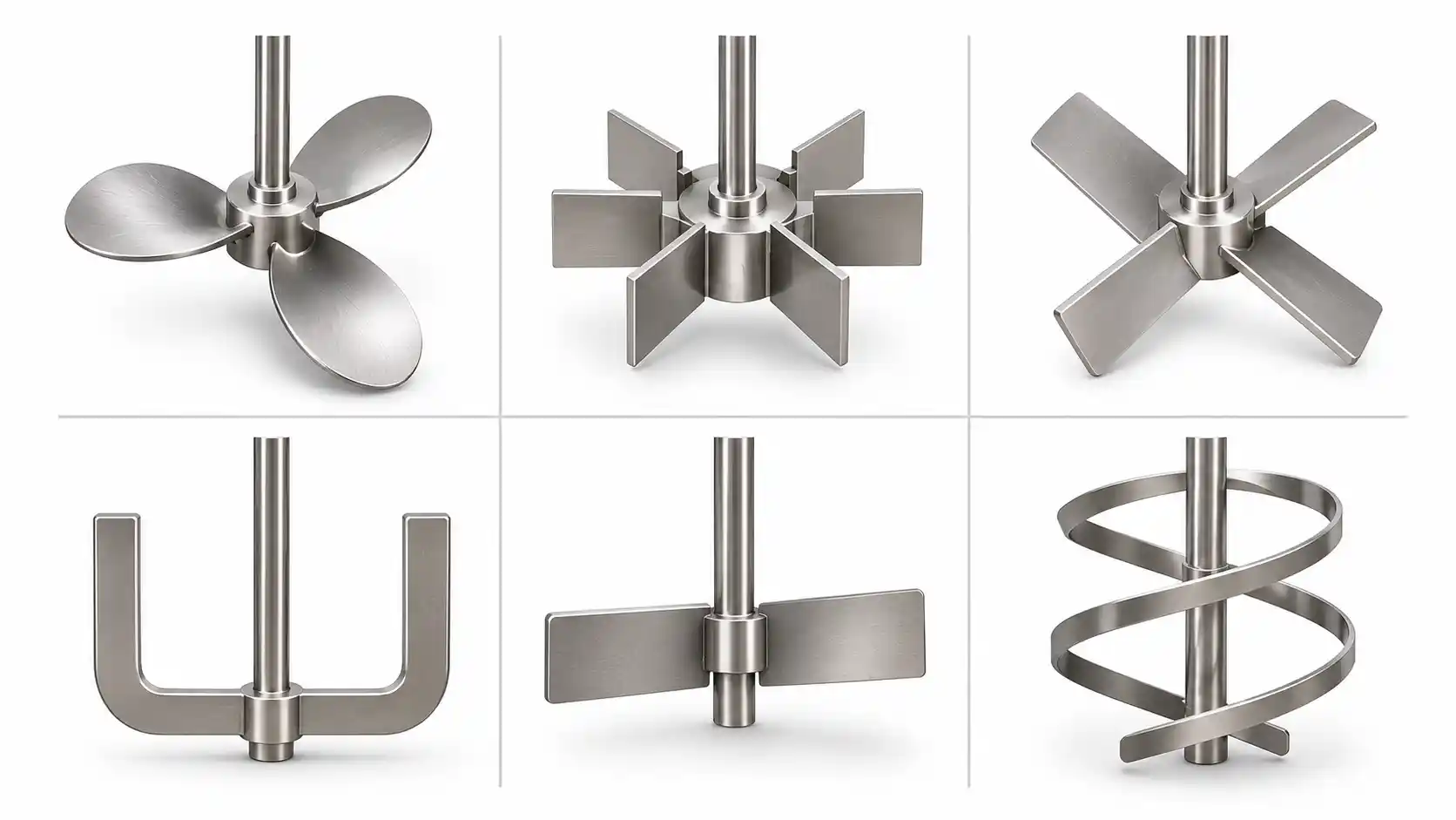
Industrial mixing is a critical process in chemical manufacturing, pharmaceutical production, food processing, water treatment, and many other industries. However, achieving a uniform mixture requires more than simply rotating a shaft inside a tank. The impeller design determines how fluids circulate, how effectively ingredients combine, and how much energy the mixing process consumes.
Understanding the types of industrial mixer impellers helps manufacturers select equipment that matches their fluid properties, production requirements, and desired mixing results. Some impellers are designed to circulate large volumes of low-viscosity liquids, while others generate stronger shear forces for gas dispersion or operate close to tank walls to handle thick materials.
Choosing the wrong impeller can result in poor blending, excessive power consumption, suspended solids settling, or inconsistent product quality. The right design can improve mixing efficiency, support temperature control, and deliver more reliable production.
What Is an Industrial Mixer Impeller?
An industrial mixer impeller is a rotating component connected to a shaft inside a mixing tank, reactor, or processing vessel. As the impeller rotates, its blades transfer mechanical energy to the surrounding fluid, creating movement that helps combine ingredients and achieve the required mixing result.
An impeller is usually part of a complete mixing system that includes a motor, gearbox, shaft, vessel, and supporting components. Depending on the application, the system may also include baffles, heating or cooling jackets, sensors, and automated controls.
The primary function of an impeller depends on the process. It may be required to:
- Blend two or more liquids into a uniform mixture.
- Keep solid particles suspended in a liquid.
- Disperse gas bubbles throughout a liquid.
- Improve heat transfer between a fluid and a tank wall.
- Help dissolve powders or other ingredients.
- Break up droplets or agglomerates through shear.
- Maintain consistent temperature and concentration throughout a vessel.
For example, a water-treatment facility may need an impeller that circulates large volumes of liquid efficiently. A chemical manufacturer producing a viscous resin may require a slow-moving impeller that generates substantial torque and moves material near the tank walls.
These different requirements explain why no single impeller design is ideal for every industrial mixing operation.
Axial-Flow vs. Radial-Flow Impellers
One of the most important ways to classify industrial mixer impellers is by the direction in which they move fluid.
The two main categories are axial-flow and radial-flow impellers. Some designs also generate mixed-flow patterns, combining axial and radial movement.
Axial-Flow Impellers
Axial-flow impellers move liquid primarily parallel to the shaft. Depending on the blade orientation and direction of rotation, the liquid may be pushed downward or upward through the tank.
This movement creates circulation throughout the vessel. Liquid travels away from the impeller and returns through surrounding areas, helping distribute ingredients and reduce concentration differences.
Axial-flow impellers are commonly used for:
- General liquid blending.
- Maintaining solids in suspension.
- Improving heat transfer.
- Circulating liquids through large tanks.
- Mixing low- to medium-viscosity fluids.
- Processes that require substantial circulation without unnecessarily high local shear.
Propeller and hydrofoil impellers are common examples of axial-flow designs. Pitched-blade turbines can also produce substantial axial flow, depending on their blade angle and operating conditions.
Main advantage: Axial-flow impellers can provide effective bulk circulation, making them useful when the objective is to move material throughout the tank.
Main limitation: Their effectiveness may decrease as viscosity increases, depending on the impeller geometry and fluid behavior.
Radial-Flow Impellers
Radial-flow impellers discharge liquid outward from the shaft toward the tank walls. This movement creates strong local flow and shear around the blades.
After reaching the walls, the fluid moves through the vessel and forms circulation patterns above and below the impeller.
Radial-flow designs are particularly useful when the process requires intensive local mixing rather than maximum bulk circulation.
Common applications include:
- Gas dispersion in liquids.
- Breaking up gas bubbles.
- Dispersing certain powders and pigments.
- Liquid-liquid dispersion.
- Processes that require relatively high local shear.
Flat-blade disc turbines, including Rushton turbines, are well-known examples of radial-flow impellers.
Main advantage: Radial-flow designs can generate the shear needed for demanding dispersion applications.
Main limitation: Their power requirements may be higher than those of some axial-flow designs under comparable conditions.
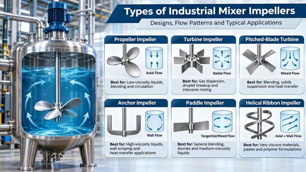
Axial-Flow vs. Radial-Flow: Comparison Table
| Feature | Axial-Flow Impeller | Radial-Flow Impeller |
|---|---|---|
| Primary flow direction | Parallel to the shaft | Outward from the shaft |
| Main mixing objective | Bulk circulation | Local shear and dispersion |
| Common examples | Propeller, hydrofoil, pitched-blade turbine | Rushton turbine, flat-blade turbine |
| Typical applications | Blending, solids suspension, heat transfer | Gas dispersion, droplet breakup, intensive mixing |
| Energy considerations | Often efficient for circulation | Depends on geometry and process duty |
| Fluid suitability | Frequently used with low- to medium-viscosity liquids | Commonly used when local shear is important |
The distinction is not absolute. Actual flow patterns depend on impeller design, rotational speed, tank geometry, baffles, fluid properties, and the impeller’s position within the vessel.
1. Propeller Impellers
Propeller impellers are compact, multi-bladed designs that produce strong axial flow. They are particularly useful for moving relatively low-viscosity liquids through a tank.
Their blades are shaped to generate fluid movement along the shaft, encouraging circulation between the upper and lower regions of the vessel.
Propeller impellers are often selected when a process requires effective blending without the high local shear associated with certain specialized mixing designs.
How Propeller Impellers Work
As the propeller rotates, its angled blades push liquid in a particular direction. The resulting flow moves through the tank and returns through surrounding areas, helping distribute dissolved ingredients and maintain a relatively uniform composition.
Depending on the mixer configuration, the propeller may be mounted vertically, at an angle, or on a portable mixing assembly.
Common Applications
Propeller impellers are commonly used for:
- Water and wastewater treatment.
- Diluting chemical solutions.
- Blending low-viscosity liquids.
- Mixing soluble ingredients.
- Circulating liquids in storage and process tanks.
- Selected pharmaceutical and food-processing operations.
Advantages
- Effective circulation in low-viscosity fluids.
- Compact design.
- Relatively simple mechanical construction.
- Suitable for many general-purpose mixing applications.
- Good circulation potential when correctly selected.
Limitations
Propeller impellers are generally less suitable for very thick materials. In high-viscosity liquids, the fluid may not circulate effectively throughout the tank, leaving poorly mixed areas.
They may also be unsuitable when a process requires substantial local shear or precise control over gas-bubble dispersion.
Best suited for: Low-viscosity liquids that require rapid circulation and general-purpose blending.
2. Turbine Impellers
Turbine impellers are widely used in industrial mixing because they can be configured to produce different combinations of fluid circulation and shear.
Unlike a simple propeller, a turbine may have several relatively short blades arranged around a central hub or disc. Blade shape, angle, number, and orientation determine how the impeller moves the fluid.
Two important configurations are radial-flow turbines and pitched-blade turbines.
Radial-Flow Turbines
Radial-flow turbines push fluid outward toward the tank walls. Flat-blade disc turbines, including Rushton turbines, are common examples.
These designs generate relatively strong local shear around the blades, making them useful when gas must be dispersed throughout a liquid or when a process requires intensive local mixing.
Typical applications include:
- Gas dispersion in chemical reactors.
- Gas-liquid contact operations.
- Selected fermentation processes.
- Certain liquid-liquid dispersion applications.
- Processes requiring stronger local turbulence.
However, not every gas-dispersion or emulsification process requires the same turbine. Final selection depends on gas flow rate, fluid properties, desired bubble characteristics, and operating conditions.
Pitched-Blade Turbines
Pitched-blade turbines use blades installed at an angle to the plane of rotation. This orientation can produce substantial axial flow along with radial movement.
They are often used when a process needs both circulation and moderate shear.
Typical applications include:
- General-purpose liquid blending.
- Suspending solid particles.
- Heat-transfer operations.
- Mixing liquids with different concentrations.
- Selected chemical-processing applications.
Advantages of Turbine Impellers
- Available in multiple configurations.
- Suitable for a broad range of mixing duties.
- Can provide either stronger shear or substantial circulation.
- Useful in many industrial reactor applications.
- Adaptable to specific gas-dispersion and blending requirements.
Limitations
Turbine impellers may require more power than simpler, high-circulation designs under comparable conditions. Their performance also depends on proper tank design, baffle placement, and impeller positioning.
A radial turbine selected for intensive gas dispersion may not be the most energy-efficient choice for a process that primarily requires bulk liquid circulation.
Best suited for: Processes that require controlled combinations of fluid circulation, local shear, and dispersion.
3. Anchor Impellers
Anchor impellers are designed for viscous liquids that are difficult to mix using conventional propellers or turbines.
Their large, frame-like structure follows the contour of the mixing tank, usually operating with a relatively small clearance between the impeller and the vessel wall.
Instead of relying mainly on high-speed circulation, an anchor impeller moves material through mechanical drag. Its large diameter helps it move material near the walls and bottom of the tank.
How Anchor Impellers Work
As the anchor rotates, its arms sweep around the vessel and push viscous material along the tank walls. This movement helps reduce stagnant regions near the surface and improves material movement around the vessel.
Anchor impellers are often used in jacketed vessels where temperature control is important. By moving material close to the heated or cooled wall, they can help improve heat transfer.
Some designs incorporate scrapers or additional blades to improve wall contact and material movement.
Common Applications
Anchor impellers are commonly used for:
- Resins and adhesives.
- Thick chemical formulations.
- Certain creams and gels.
- Selected paints and coatings.
- Viscous food products.
- Materials that require controlled heating or cooling.
Advantages
- Suitable for high-viscosity fluids.
- Moves material close to tank walls.
- Can support heat transfer in jacketed vessels.
- Helps reduce stagnant regions near the vessel perimeter.
- Can be combined with other mixing elements.
Limitations
Anchor impellers generally operate at lower speeds than propellers. Their large diameter and high torque requirements may also increase equipment costs.
A basic anchor may provide limited vertical circulation, particularly in tall vessels. Depending on the process, additional blades, a secondary impeller, or a different close-clearance design may be needed.
Best suited for: High-viscosity materials that require wall-to-wall movement and controlled temperature management.
4. Paddle Impellers
Paddle impellers use relatively broad, flat, or gently angled blades attached to a rotating shaft.
Their performance depends on the number and orientation of the blades, the impeller diameter, and the fluid’s properties. Some paddle designs create mainly tangential movement, while angled blades can introduce additional axial or radial flow.
Paddle mixers are often used for straightforward blending tasks where moderate circulation and relatively simple mechanical construction are desirable.
How Paddle Impellers Work
As the shaft rotates, the blades push material through the vessel. Depending on the design, the fluid may move around the tank, across the vessel, or through a combination of flow paths.
Paddle impellers can operate at relatively low speeds when handling heavier liquids or certain solid-liquid mixtures.
However, the term paddle impeller covers several designs. A small, flat-blade paddle and a large, close-clearance paddle assembly should not be treated as interchangeable.
Common Applications
- General liquid blending.
- Mixing certain chemical solutions.
- Solid-liquid suspension under suitable conditions.
- Slurry preparation.
- Selected low- to medium-viscosity applications.
- Processes that benefit from simple, robust mixing equipment.
Advantages
- Relatively simple construction.
- Can be adapted to different tank sizes.
- Suitable for selected low-speed mixing duties.
- Available in a range of blade configurations.
Limitations
A conventional paddle may not generate enough circulation for demanding mixing applications. It can also be less effective in very viscous materials if the blade arrangement does not move the entire batch.
For applications involving settling solids, engineers must confirm that the selected paddle produces sufficient circulation throughout the vessel.
Best suited for: General-purpose blending and selected low-speed mixing applications where the required flow pattern matches the paddle design.
5. Hydrofoil Impellers
Hydrofoil impellers are designed to move liquid efficiently while producing substantial axial circulation.
Their blades have a streamlined profile that helps generate fluid movement with relatively low resistance compared with some conventional blade designs.
Hydrofoils are often considered when a process requires high circulation, energy efficiency, or reliable solids suspension.
How Hydrofoil Impellers Work
As the impeller rotates, its shaped blades accelerate liquid along the shaft direction. This movement helps establish circulation loops throughout the vessel.
The resulting flow can move material through a large portion of the tank without relying exclusively on high local turbulence.
Common Applications
- Solid suspension.
- Bulk liquid blending.
- Water and wastewater treatment.
- Chemical processing.
- Applications where circulation and energy consumption are important.
Advantages
- Efficient bulk circulation in suitable operating conditions.
- Useful for solid suspension.
- Can provide favorable mixing performance at relatively low power demand.
- Suitable for many large-volume mixing applications.
Limitations
Hydrofoils may not be ideal when a process requires intense local shear or specialized gas-dispersion performance. Their effectiveness also depends on fluid properties, tank geometry, and operating conditions.
Best suited for: Processes requiring efficient liquid circulation and solids suspension.
6. Helical Ribbon Impellers
Helical ribbon impellers are specialized designs for mixing highly viscous liquids and materials that do not circulate easily.
Their spiral-shaped blades move close to the vessel wall and help transport material vertically through the tank.
Compared with a conventional anchor, a helical ribbon is designed to generate more substantial axial movement while maintaining close clearance from the vessel wall.
How Helical Ribbon Impellers Work
As the ribbon rotates, it pushes viscous material along the vessel and encourages movement between different vertical regions.
The close-clearance geometry helps reduce stagnant areas that can develop when thick materials are mixed with smaller, conventional impellers.
Depending on the system, the design may be configured to move material upward or downward along the vessel wall.
Common Applications
- Highly viscous polymers.
- Pastes and thick formulations.
- Certain adhesives and resins.
- Concentrated chemical products.
- Materials that require relatively uniform temperature and composition.
Advantages
- Suitable for high-viscosity mixing.
- Provides close-clearance movement near the vessel wall.
- Can improve vertical material circulation.
- Useful for applications where conventional impellers leave poorly mixed regions.
Limitations
Helical ribbon impellers can require substantial torque and specialized mechanical design. Their performance depends on vessel geometry, material behavior, operating speed, and the available drive system.
Best suited for: Highly viscous fluids that require both close-clearance movement and improved circulation through the vessel.
Which Impeller Is Best for High-Viscosity Liquids?
High-viscosity liquids behave differently from water-like fluids. Their resistance to movement makes it difficult for conventional high-speed impellers to circulate material through an entire tank.
In these applications, the mixing system may require a larger impeller diameter, higher torque, close-clearance blades, or specialized geometries.
Anchor and helical ribbon impellers are common options, but the best choice depends on the required movement and the properties of the material.
Anchor vs. Helical Ribbon Impellers
| Feature | Anchor Impeller | Helical Ribbon Impeller |
|---|---|---|
| General design | Frame-like structure following the tank wall | Spiral-shaped blade following the vessel wall |
| Main movement | Primarily wall-following and tangential | Wall-following movement with stronger axial transport |
| Common duty | Viscous blending and heat-transfer support | Viscous blending requiring more vertical circulation |
| Typical applications | Resins, gels, thick formulations | Polymers, pastes, concentrated formulations |
| Main consideration | Vertical mixing may be limited | Higher torque and more specialized design may be required |
As viscosity increases, the fluid may circulate less readily around the tank. A small impeller can move the material immediately surrounding its blades while leaving distant regions relatively stagnant.
A larger, close-clearance impeller can help address this challenge by mechanically moving material across a greater portion of the vessel.
However, higher viscosity does not automatically mean that the largest possible impeller is best. Engineers must consider vessel dimensions, required torque, fluid behavior, motor capacity, and the mixing objective.
Choosing Impellers for Gas Dispersion
Gas dispersion occurs when a gas is introduced into a liquid and distributed as bubbles throughout the vessel.
This operation is important in selected chemical reactions, fermentation processes, and other gas-liquid applications.
A gas-dispersion impeller must create appropriate flow and shear to distribute the gas effectively. Radial-flow disc turbines are commonly used for this purpose, although the best design depends on the process.
How Gas Dispersion Works
Gas enters the mixing vessel through a sparger or another gas-delivery arrangement. The rotating impeller interacts with the incoming gas and surrounding liquid, helping distribute the gas into bubbles.
The bubbles provide an interface between the gas and liquid. In suitable systems, this interface supports mass transfer between the phases.
Mixing performance depends on several variables:
- Impeller type and diameter.
- Rotational speed.
- Gas flow rate.
- Gas-entry location.
- Tank diameter and liquid depth.
- Fluid viscosity and surface properties.
- Required mass-transfer performance.
Increasing speed may improve gas distribution under some operating conditions, but it can also increase power consumption and mechanical stress. Excessive gas flow may also reduce impeller performance or cause unstable operation.
For this reason, gas dispersion should be evaluated as a complete mixing-system requirement rather than an impeller-only decision.
Choosing Impellers for Solid Suspension
Solid suspension is the process of keeping solid particles distributed throughout a liquid instead of allowing them to settle at the bottom of the tank.
It is important in mineral processing, chemical manufacturing, water treatment, and other operations involving powders, crystals, or insoluble particles.
The objective is not always to dissolve the solids. Instead, the mixing system must generate enough liquid movement to keep the particles suspended at the required level.
Which Impeller Is Best for Solid Suspension?
Axial-flow impellers are often effective for solid suspension because they generate substantial circulation through the vessel.
Hydrofoils and pitched-blade turbines are common options. However, the best design depends on particle size, density, concentration, settling velocity, liquid viscosity, and tank geometry.
The impeller must create sufficient movement near the bottom of the tank to prevent unwanted accumulation.
Important Design Considerations
When selecting an impeller for solid suspension, engineers should evaluate:
- Particle size and density.
- Solids concentration.
- Liquid viscosity.
- Tank-bottom geometry.
- Impeller clearance from the bottom.
- Required degree of suspension.
- Potential particle damage or attrition.
- Motor power and operating cost.
If the impeller is too small or operates too slowly, particles may settle. If it operates unnecessarily fast, energy consumption can rise without providing a meaningful improvement in process performance.
How Mixing Speed Affects Impeller Performance
Mixing speed, measured in revolutions per minute (RPM), affects fluid movement, local shear, and the mechanical power required by the mixer.
However, higher speed does not always produce better mixing.
A propeller operating at relatively high speed may circulate a low-viscosity liquid effectively. A large anchor impeller may operate much more slowly because it needs to move a thick material while generating substantial torque.
The appropriate speed depends on impeller geometry, fluid properties, tank dimensions, and process requirements.
What Happens When Mixing Speed Is Too Low?
Insufficient speed may cause:
- Poor blending and uneven concentrations.
- Solids settling at the bottom of the tank.
- Inadequate gas dispersion.
- Slow dissolution of ingredients.
- Uneven temperature distribution.
What Happens When Mixing Speed Is Too High?
Excessive speed can lead to:
- Higher energy consumption.
- Unwanted vortex formation.
- Increased air entrainment.
- Excessive shear for sensitive materials.
- Greater mechanical loads on shafts and gearboxes.
- Unwanted heat generation.
The correct operating point should be established through engineering calculations, supplier data, and process testing where necessary.
Variable-frequency drives can help adjust motor speed to match changing production requirements, provided the mixer, motor, gearbox, and impeller are suitable for the operating range.
How Tank Geometry Affects Impeller Selection
Impeller performance depends on the tank as well as the rotating component.
Two mixers using the same impeller can produce different results when installed in vessels with different dimensions, internal structures, or operating conditions.
Important tank-related factors include tank diameter, liquid height, bottom shape, internal baffles, and the impeller’s position.
Tank Diameter and Liquid Height
The ratio between impeller diameter and tank diameter affects circulation, shear, and power requirements.
A relatively small impeller may be effective in a compact vessel but may fail to circulate liquid adequately in a much larger tank.
Similarly, a tall vessel may require more than one impeller to distribute mixing energy across the entire liquid volume.
The correct diameter ratio varies with the impeller design and process. It should not be selected using a single universal rule.
Baffles and Vortex Formation
In a centrally mounted mixer, the liquid can begin rotating as a single mass rather than circulating effectively through the tank.
This can create a vortex near the liquid surface and reduce mixing effectiveness.
Baffles are vertical plates installed along the tank wall to interrupt this circular movement. Properly designed baffles help redirect fluid into more useful circulation patterns.
However, baffle requirements depend on the mixing system. Close-clearance anchor mixers and some other configurations may operate without conventional baffles.
Impeller Position and Clearance
The distance between the impeller and the tank bottom affects circulation near the floor of the vessel.
If this clearance is unsuitable, solids may accumulate in areas where fluid movement is weak.
In tall tanks, multiple impellers may be used to improve circulation across different liquid levels. Their spacing and orientation must be selected according to the flow patterns they generate.
The key principle: Impeller selection and tank design should be treated as connected engineering decisions.
Why Impeller Diameter Matters
Impeller diameter influences the volume of fluid moved, the flow pattern, and the power required to rotate the impeller.
A larger impeller can often move more liquid, but it also places greater demands on the drive system.
The relationship between diameter, speed, and power is particularly important when scaling up a mixing process from a laboratory vessel to an industrial tank.
For geometrically similar systems operating in comparable turbulent conditions, impeller power is often estimated using:
P = Np × ρ × N³ × D⁵
Where:
- P = power required by the impeller.
- Np = dimensionless power number for the impeller and operating conditions.
- ρ = fluid density.
- N = rotational speed in revolutions per second.
- D = impeller diameter.
This relationship illustrates why diameter and speed must be considered carefully. Under the stated conditions, power increases strongly as either variable increases.
However, this equation is not a universal predictor for every mixer. The power number can change with Reynolds number, fluid behavior, impeller geometry, and operating conditions. High-viscosity and non-Newtonian systems may require different calculations.
Engineers should confirm the actual power requirements before specifying a motor or gearbox.
Comparison of the Main Industrial Mixer Impeller Types
The following table summarizes the common designs and their typical uses.
| Impeller Type | Primary Flow Pattern | Typical Fluid Characteristics | Main Applications | Key Consideration |
|---|---|---|---|---|
| Propeller | Axial | Low viscosity | Liquid blending and circulation | Less effective in very thick fluids |
| Radial turbine | Radial | Often low to medium viscosity, depending on duty | Gas dispersion and intensive local mixing | Shear and power demand must be evaluated |
| Pitched-blade turbine | Mixed, often axial-dominant | Low to medium viscosity | Blending, suspension, heat transfer | Performance depends on blade angle and geometry |
| Anchor | Primarily tangential and wall-following | High viscosity | Resins, gels, viscous formulations | High torque and limited vertical circulation in some designs |
| Paddle | Tangential or mixed, depending on design | Application-dependent | General blending and selected suspension duties | Blade arrangement determines circulation |
| Helical ribbon | Close-clearance, with axial and tangential movement | High viscosity | Polymers, pastes, concentrated materials | Requires suitable torque and vessel clearance |
| Hydrofoil | Axial | Commonly low to medium viscosity | Efficient circulation and solids suspension | May be unsuitable for duties requiring high local shear |
These categories provide a starting point rather than a final specification. The actual operating range of each impeller depends on its geometry and the properties of the material being processed.
How to Choose the Right Impeller for an Industrial Process
Selecting an impeller starts with the required process outcome. Engineers should identify what the mixer must achieve before choosing a specific blade design.
1. Identify the Main Mixing Objective
Determine whether the process requires liquid blending, gas dispersion, solid suspension, powder incorporation, or high-viscosity mixing.
Each objective places different demands on the impeller.
For example, a process that requires rapid liquid circulation may benefit from an axial-flow design. A gas-dispersion application may require a radial-flow turbine to generate suitable local shear.
2. Evaluate Fluid Viscosity
Viscosity strongly influences how easily the material moves through the tank.
Low-viscosity liquids can often be mixed effectively with propellers or hydrofoils. Higher-viscosity products may require anchors, helical ribbons, or other close-clearance designs.
For non-Newtonian materials, viscosity may change with shear rate. In such cases, a single viscosity value may not adequately describe the fluid’s behavior during mixing.
3. Determine Whether Shear Is Required
Some processes benefit from high local shear, particularly when dispersing gas bubbles or breaking up droplets and agglomerates.
Other processes prioritize gentle circulation to avoid damaging shear-sensitive materials.
The impeller should therefore provide the required balance between fluid movement and shear rather than simply maximizing either one.
4. Assess the Tank Dimensions
Review the tank diameter, liquid depth, bottom geometry, available mounting space, and existing internal structures.
These factors influence impeller diameter, shaft length, impeller position, and whether multiple impellers are necessary.
5. Calculate Power and Torque Requirements
The motor and gearbox must provide sufficient power and torque under actual operating conditions.
This is particularly important for viscous materials, where starting torque can be significant.
The specification should account for fluid properties, impeller geometry, operating speed, and potential changes in viscosity during production.
6. Consider Materials and Chemical Compatibility
The impeller material must withstand the fluid’s chemical properties and operating temperature.
Stainless steel is common in many industrial mixing systems, but corrosive chemicals, aggressive cleaning agents, or specialized process requirements may call for other alloys or protective materials.
Material selection should also consider product contamination risks, cleanability, and applicable industry standards.
7. Evaluate Energy Consumption and Maintenance
A mixer should deliver the required process performance without unnecessary energy use or maintenance costs.
Review motor efficiency, gearbox requirements, seal design, shaft loading, cleaning access, and the availability of replacement components.
The lowest initial purchase price does not necessarily represent the lowest total cost of ownership.
Common Mistakes When Selecting Industrial Mixer Impellers
Even a well-manufactured impeller may deliver poor results when its design does not match the process.
Avoid these common mistakes:
Choosing an impeller based only on RPM: Speed alone does not determine mixing performance. Diameter, blade geometry, viscosity, and tank dimensions also matter.
Ignoring fluid viscosity: A design that performs well with water may be unsuitable for a thick resin or concentrated chemical formulation.
Using high speed to solve every mixing problem: Increasing speed can increase power consumption without eliminating poorly mixed regions elsewhere in the tank.
Overlooking tank geometry: An impeller must be evaluated together with tank dimensions, baffles, bottom clearance, and liquid depth.
Selecting a gas-dispersion impeller for a circulation-dominated process: The design that generates the required shear may not be the most efficient choice for bulk fluid movement.
Failing to check motor and gearbox requirements: An impeller that exceeds the drive system’s torque or power capacity can lead to poor performance and mechanical problems.
Ignoring future operating conditions: Changes in formulation, solids concentration, temperature, or production capacity may alter the mixer requirements.
A systematic engineering assessment helps prevent these problems and improves long-term equipment reliability.
Frequently Asked Questions
What are the main types of industrial mixer impellers?
The main types include propeller impellers, radial-flow turbines, pitched-blade turbines, anchor impellers, paddle impellers, helical-ribbon impellers, and hydrofoil impellers. Each design creates a different flow pattern and is suited to particular mixing requirements.
Which impeller is best for high-viscosity liquids?
Anchor and helical-ribbon impellers are common choices for high-viscosity liquids. Anchor designs provide wall-following movement, while helical ribbons can offer stronger axial transport. The final choice depends on viscosity, tank geometry, required circulation, and torque requirements.
What is the difference between axial-flow and radial-flow impellers?
Axial-flow impellers move fluid primarily parallel to the shaft, supporting bulk circulation and blending. Radial-flow impellers discharge fluid outward toward the tank walls and are commonly used when stronger local shear or gas dispersion is required.
Which impeller is best for gas dispersion?
Radial-flow disc turbines, including Rushton turbines, are widely used for gas dispersion. However, the best design depends on gas flow rate, liquid properties, required mass transfer, tank dimensions, and operating conditions.
Which impeller is suitable for solid suspension?
Axial-flow designs such as hydrofoils and pitched-blade turbines are often effective for solid suspension because they generate substantial circulation. Final selection depends on particle properties, liquid viscosity, solids concentration, and tank geometry.
Does a larger impeller always provide better mixing?
No. A larger impeller may increase fluid movement, but it can also increase power and torque requirements. Its effectiveness depends on the impeller design, rotational speed, fluid properties, and tank dimensions.
How does mixing speed affect energy consumption?
Increasing rotational speed generally increases power demand significantly in comparable turbulent operating conditions. The exact relationship depends on the impeller and fluid regime. Engineers should select a speed that meets process requirements without unnecessary energy consumption.
Can one impeller handle multiple mixing tasks?
Yes, some impellers can perform several functions. For example, a pitched-blade turbine may support blending, solids suspension, and heat transfer. However, a single design may not optimize every task, particularly when the process requires both high circulation and intensive gas dispersion.
Conclusion
Selecting the right impeller is essential for achieving consistent mixing, reliable production, and efficient energy use. Propellers and hydrofoils are commonly used for bulk circulation, turbine impellers support a range of blending and dispersion duties, and anchor or helical-ribbon designs help manage high-viscosity materials.
The best choice depends on more than the impeller itself. Fluid viscosity, required shear, mixing speed, tank geometry, impeller diameter, power requirements, and material compatibility must all be considered together.
For manufacturers planning a new mixing system or upgrading an existing process, understanding these factors provides a practical starting point for equipment selection. Explore Mekantra Technologies’ chemical processing equipment solutions to learn more about industrial mixing and blending tanks, reactors, and related process equipment.
At Mekantra Technologies, the focus is on helping industrial businesses identify suitable machinery and processing solutions for their technical and operational requirements.

Mekantra Engineering Team
The technical voice of Mekantra. Our team consists of sourcing specialists, mechanical engineers, and logistics experts dedicated to providing transparent insights and high-performance solutions for the global manufacturing sector.
Mekantra Engineering Team
The technical voice of Mekantra. Our team consists of sourcing specialists, mechanical engineers, and logistics experts dedicated to providing transparent insights and high-performance solutions for the global manufacturing sector.