Carding Machine Alignment: Fiber Mechanics & Tips
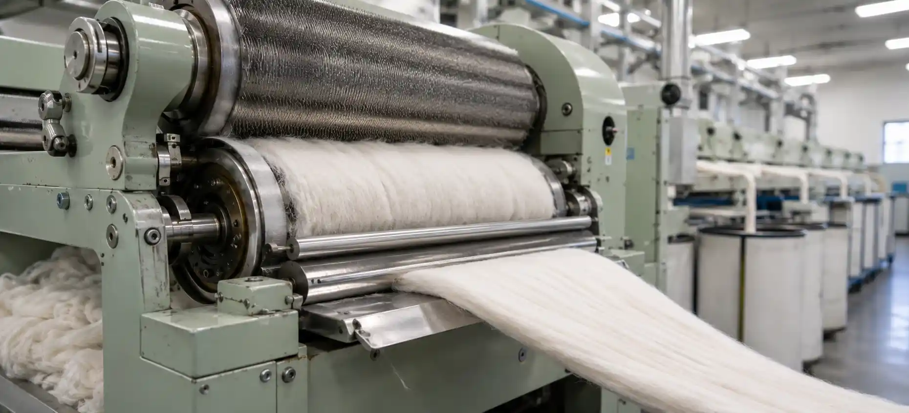
In modern textile manufacturing, woven fabric quality is determined long before yarn reaches the weaving shed. While ring spinning frames and automatic winders refine thread consistency, the true structural foundation of spun yarn is laid in the blowroom and carding section.
The carding machine often termed the heart of the spinning mill serves a singular, critical function: converting a chaotic, three-dimensional mass of raw tufts into a continuous, highly uniform, one-dimensional fiber strand known as the card sliver.
Raw natural fibers like cotton or synthetic staple fibers like polyester arrive at the mill in tightly compressed bales. These fibers are tangled, multi-directional, and contaminated with trash particles, seed fragments, and mechanical knots known as neps.
Carding changes this trajectory entirely. By subjecting raw stock to rigorous opening, cleaning, and mechanical combing, carding machines force microscopic fiber strands into parallel alignment along the longitudinal axis of the sliver. Precision fiber alignment at the carding stage is the ultimate prerequisite for producing strong, uniform yarn capable of withstanding the extreme tension of modern weaving machinery.
Why Is Individual Fiber Alignment the Critical Factor in Spun Yarn Quality?
To understand the necessity of fiber alignment, one must examine the physics of yarn tenacity and structural mass distribution. Spun yarn derives its strength from the surface friction and cohesive clamping forces generated between overlapping fibers when twist is inserted during spinning.
Key Factors Influencing Spun Yarn Quality
- Tensile Strength & Load Distribution: When fibers lie parallel in the machine direction, tensile loads distribute evenly across every fiber cross-section. Each fiber contributes its full load-bearing capacity to the strand. Misaligned or folded fibers fail to carry load, causing localized stress points where yarn snaps under low tension.
- Yarn Hairiness & Surface Smoothness: Fiber orientation dictates surface topography. Unparallel fibers leave fiber ends protruding outward from the core, creating high hairiness (elevated S3 values). Parallel alignment keeps fiber ends tucked into the core, drastically reducing fiber shedding and clearer waste.
- Mass Variation (Uster CV%): Uncontrolled fiber orientation degrades yarn evenness. Tangled fiber hooks prevent drafting rollers from pulling fibers smoothly during drawing. This causes whole fiber clusters to drag forward together, creating alternating thick and thin places in the sliver.
| Quality Parameter | Poor Alignment (Uncontrolled Carding) | High Alignment (Optimized Carding) |
| Yarn Tenacity (cN/tex) | 12.5 – 14.0 | 17.5 – 19.5 |
| Uster Mass CV% | > 16.5% | < 12.0% |
| Nep Count (per 1,000m) | > 180 | < 45 |
| Hairiness Index (H) | 7.8 – 9.2 | 4.8 – 5.5 |
How Do Machine Components Mechanically Force Fibers into Parallel Alignment?
Transforming a disorganized fiber lap into a perfectly aligned sliver requires a progressive mechanical strategy. A modern high-production carding machine accomplishes this through three continuous operational zones.
                      [ Moving Flat Tops ]
                     |   /   /   /   /   |  <-- Slow Speed (Wire angled opposite)
---------------------------------------------------------------------------------
  Carding Zone Gauge: 0.175 mm - 0.250 mm (Micro-Gap Combs Individual Fibers)
---------------------------------------------------------------------------------
                     |   \   \   \   \   |  <-- High Speed (1,500 - 2,100 m/min)
                     [  Main Cylinder   ]
Step 1: The Licker-In (Taker-In) Primary Opening & Tuft Separation
- High-Speed Combing: Rotating at 800 to 1,200 RPM, coarse saw-tooth wire combs through incoming raw fiber lap to break large tufts into tiny micro-clusters.
- Centrifugal Waste Extraction: High rotational force hurls heavy impurities, seed fragments, and dirt outward through adjustable mote knives and under-casing grids.
- Cylinder Protection: Isolates individual fiber strands so raw material enters the main carding zone cleanly without clogging wire teeth.
Step 2: Main Cylinder vs. Flat Tops Core Carding Action
- Differential Speed Drag: The main cylinder rotates at high linear speeds (1,500 to 2,100 m/min) beneath slow-moving flat tops, creating intense mechanical drag across fiber strands.
- Opposing Wire Angles: Forward-slanted cylinder wire teeth pull fibers past backward-slanted flat wire teeth across narrow micro-gauges (0.175 mm to 0.250 mm).
- Hook Straightening Mechanics: Opposing wire points grip both ends of individual fibers. Fast cylinder motion pulls leading ends forward while slow flats hold trailing ends back, straightening folded fiber hooks along the machine direction.
- Nep Retention & Removal: Short, uncombable fiber tangles (neps) remain caught on flat wire teeth and are brushed away as flat waste by stripping rollers.
Step 3: The Doffer Transfer Web Formation & Consolidation
- Controlled Speed Deceleration: The doffer rotates at a much lower speed than the main cylinder (1:15 to 1:30 ratio), acting as a gentle brake to catch moving fibers.
- Preserving Parallel Alignment: Reverse-angled doffer wire condenses fast-moving parallel fibers into a smooth, uniform two-dimensional fiber web layer.
- 1D Sliver Condensing: Stripper rollers lift the fiber web off the doffer and draw it through a condensing trumpet, creating a strong, highly parallelized one-dimensional card sliver.
When Does Over-Carding Occur, and What Are Its Hidden Costs?
Operating a carding machine with overly aggressive settings is a common shop-floor error. Pushing mechanical parameters beyond optimal limits breaks delicate fibers and reduces structural yarn quality.
Hidden Risks of Over-Carding
- Fiber Rupture: Excessive cylinder velocity or overly tight cylinder-to-flat gauges crush fibers between opposing wire teeth rather than combing them softly.
- Increased Short Fiber Content (SFC): Snapping natural or synthetic fibers increases the ratio of short fibers (< 12.7 mm). Short fibers cause excessive fly waste and degrade yarn tenacity.
- Secondary Nep Generation: Broken fiber ends recoil and re-tangle under air turbulence inside the cylinder under-casing, manufacturing small mechanical knots that cannot be combed out later.
- Increased Machine Wear: Overly tight gauges accelerate wire wear, requiring frequent wire grinding and premature clothing replacement.
Why Does Fiber Alignment Directly Impact Weaving Performance on Air-Jet and Rapier Looms?
Card sliver structural quality directly controls production efficiency on modern weaving looms. Today’s high-speed weaving sheds operate under tight mechanical tolerances, making loom performance highly sensitive to yarn defects caused by poor carding alignment.
For a deeper dive into loom mechanics, read our technical overview of Modern Looms: Air Jet vs. Rapier Weaving Technology.
Carding Efficiency (Parallel Alignment & Low Neps)
                       │
                       ▼
High Yarn Tenacity & Minimal Surface Hairiness
                       │
 ┌─────────────────────┴─────────────────────┐
 ▼                                           ▼
Air-Jet Weft Insertion                     Rapier Warp Tension
• Unobstructed air flow                    • High tensile threshold
• Zero nozzle clogging                     • Resistance to cyclic stress
• Minimal fill stops                       • Minimal warp breakages
 └─────────────────────┬─────────────────────┘
                       ▼
Optimal Weaving Shed Efficiency (> 95% Run-Rate)
Impact on High-Speed Weaving Technologies
- Air-Jet Weft Insertion Constraints: Air-jet looms shoot weft yarn through profile reeds using compressed air at speeds over 1,200 PPM. Poorly aligned card sliver produces hairy yarn, creating aerodynamic drag that slows weft travel, clogs nozzles with fly waste, and causes frequent filling stops.
- Rapier Loom Mechanical Tension: Rapier grippers pull weft yarn across warp sheds under heavy cyclic tension. Weak yarn spots caused by misaligned card sliver snap instantly under tensile shock, causing warp breaks and halting production.
- Fabric Surface Uniformity: Perfectly aligned card sliver produces yarn with uniform cross-sectional density, preventing streaking and uneven dye uptake during fabric finishing.
Upgrading Your Mill’s Carding Infrastructure
Achieving consistent fiber alignment relies heavily on the mechanical precision of your processing equipment. Modern carding engines built with heavy-duty frames, high-speed precision cylinders, and automated wire clothing settings reduce mechanical fiber drag and maintain micro-gauge clearances during continuous multi-shift production.
By investing in high-efficiency Textile Machinery, mill operators can maintain uniform sliver density, protect staple length from severe rupture, and eliminate processing bottlenecks between fiber preparation and high-speed weaving. Advanced machinery layout ensures that the parallelization achieved during carding directly translates into higher yarn tenacity, lower Uster CV%, and maximum loom run-rates.
How Are Smart Auto-Levelers and Sensor Technologies Modernizing Carding?
Modern high-production carding machines integrate digital monitoring and automated control systems to maintain consistent sliver quality despite natural variations in raw fiber bales.
[ Raw Fiber Feed ] ──> [ Feed Optical Sensor ] ──> [ Closed-Loop Controller ]
                                                              │
[ Delivered Sliver ] <── [ Output Measuring Disc ] <──────────┘
                         (Adjusts Feed Roller Speed in Real-Time)
Advanced Carding Innovations
- Open-Loop Feed Auto-Leveling: Optical sensors scan incoming fiber lap thickness before the licker-in, adjusting feed roller speeds to maintain uniform mass delivery to the cylinder.
- Closed-Loop Delivery Auto-Leveling: Precision measuring discs monitor delivered sliver mass at the coiler head, adjusting draft ratios in real-time to keep count variation under +/- 1.0% Uster CV.
- Adaptive Recycled Fiber Processing: Variable-speed drives and specialized wire clothing allow operators to fine-tune flat-to-cylinder speed ratios, safely aligning delicate, short-staple recycled cotton and rPET fibers.
Conclusion & Actionable Shop-Floor Checklist
Achieving high yarn strength, low mass variation, and high weaving efficiency requires complete control over fiber alignment in the carding room. Balancing wire clothing selection, surface speeds, and mechanical clearances protects fiber length while maximizing nep removal.
Actionable Shop-Floor Checklist for Mill Operators
- Check Gauge Clearances: Inspect cylinder-to-flat gaps weekly using feeler gauges, maintaining strict clearances between 0.175 mm and 0.250 mm.
- Monitor Nep Removal Efficiency (NRE): Test raw cotton neps against delivered sliver neps daily using AFIS testing, maintaining an NRE above 85%.
- Audit Wire Tooth Sharpness: Inspect card clothing every 500 operating hours and re-grind rounded wire teeth immediately to preserve combing efficiency.
- Calibrate Auto-Levelers: Test short-term and long-term auto-leveler sensor discs regularly to keep sliver mass variation within < 1.0% CV.
- Match Wire Profile to Fiber Type: Select acute wire angles for synthetic staple fibers and gentler tooth profiles for fine natural cottons.

Mekantra Engineering Team
The technical voice of Mekantra. Our team consists of sourcing specialists, mechanical engineers, and logistics experts dedicated to providing transparent insights and high-performance solutions for the global manufacturing sector.
Mekantra Engineering Team
The technical voice of Mekantra. Our team consists of sourcing specialists, mechanical engineers, and logistics experts dedicated to providing transparent insights and high-performance solutions for the global manufacturing sector.