How Does a Steel Coil Slitting Line Work? (Full Guide)
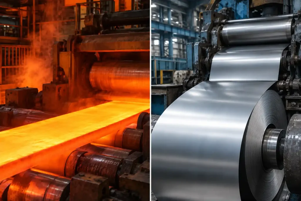
Steel coils are fundamental raw materials across global manufacturing. However, steel mills typically produce metal coils in wide standard master widths, often spanning from 36 inches to over 72 inches. Because downstream applications such as stamping presses, roll forming machines, tube mills, and bracket manufacturing require much narrower strips, master coils must be precisely cut down to size.
This is where a steel coil slitting line becomes vital.
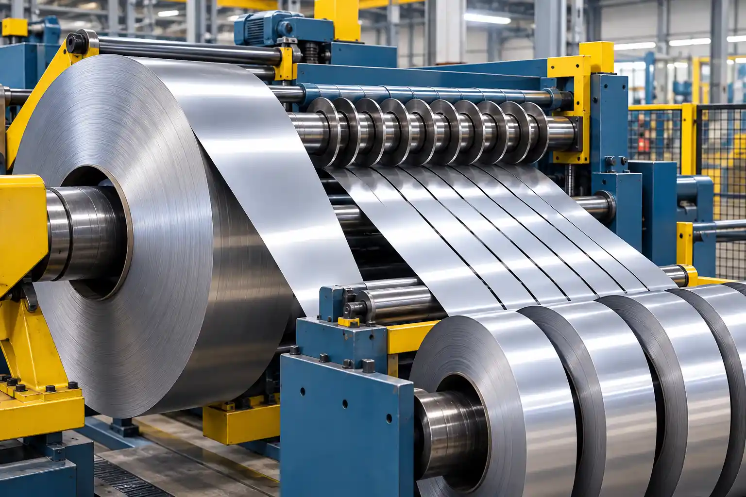
A steel coil slitting line is a continuous industrial machinery system designed to uncoil a wide master metal roll, longitudinally cut (slit) it into narrower widths using precise rotary knives, and recoil the resulting strips into individual, tightly wound coils known as “mults” or “slit coils.”
Understanding how a steel coil slitting line work requires examining every physical stage of this mechanical process. In this complete guide, we will break down the entire coil slitting process step by step, explain the mechanics behind width control and edge quality, and examine how industrial manufacturing lines achieve tight dimensional tolerances.
What is the Coil Slitting Process?
The coil slitting process is a continuous longitudinal shearing operation. Unlike guillotine or cross-cutting shears that chop metal across its width, a coil slitting machine runs the metal sheet lengthwise between two rotating arbors fitted with circular rotary blades.
The process does not remove material in the form of chips like milling or drilling does. Instead, it applies high torsional shear stress to the top and bottom surfaces of the metal sheet, causing it to fracture cleanly along pre-determined parallel lines.
The main objectives of a high-performance metal coil slitting operation are:
- Converting large master coils into narrower widths (“mults”).
- Maintaining tight width tolerances (often within thousandths of an inch).
- Producing smooth, burr-free edges that meet strict engineering standards.
- Rewinding the slit strips into tight, uniform finished coils ready for transport or immediate downstream fabrication.
Key Components of a Steel Coil Slitting Line
Before diving into the step-by-step sequence of operation, it helps to understand the core machinery components that make up a standard steel coil slitting line. Each component plays a specific role in managing material flow, tension, or cutting accuracy.
| Machine Component | Main Function | Technical Significance |
|---|---|---|
| Hydraulic Coil Car | Transports and aligns the master coil with the uncoiler shaft. | Heavy load capacity; prevents telescoping or physical damage during loading. |
| Uncoiler (Decoiler) | Holds the master coil and controls feed speed using back-tension. | Features hydraulically expanding mandrels and hold-down rolls for safety. |
| Peeler & Pinch Rolls | Unpacks the outer wrap and feeds the leading edge forward. | Flattens coil set curvature and maintains constant strip trajectory. |
| Edge Position Control (EPC) | Automatically shifts the line laterally to center the incoming strip. | Ensures uniform side trimming and straight travel into the cutter. |
| Slitting Head (Arbors) | Holds rotating knives, spacers, and stripper rings to shear the metal. | Machined to extreme mechanical tolerances to prevent shaft deflection. |
| Scrap Chopper / Winder | Collects and processes the trimmed outer scrap edges continuously. | Prevents line jamming and creates compact scrap material for recycling. |
| Looping Pit | Accommodates length variations across individual slit strips. | Solves speed differences caused by natural coil crown thickness variations. |
| Tension Stand | Applies uniform friction drag to each individual slit mult. | Guarantees tight, uniform rewinding without telescoping. |
| Recoiler Drum | Grips all slit strips and pulls them through the tensioner onto a single shaft. | Driven by high-torque motors to form dense, tightly wound finished coils. |
How Does a Steel Coil Slitting Line Work? A Step-by-Step Breakdown
The coil slitting process steps follow a continuous sequence where raw metal is fed, straightened, cut, tensioned, and rewound. Here is how each stage operates in real time.
Step 1: Master Coil Loading and Positioning
The process begins at the entry section of the slitting facility. A wide master steel coil which can weigh anywhere from 5 to 30 metric tons—is retrieved from raw material storage using an overhead crane or forklift and placed onto a hydraulic coil car.
The coil car runs on heavy-duty floor rails. It lifts the massive coil vertically and moves it horizontally, aligning the central eye (inside diameter) of the coil with the expanding shaft of the uncoiler.
Once aligned, the coil car slides the coil directly onto the uncoiler mandrel.
Step 2: Uncoiling (Decoiling) Under Tension
When the master coil is fully seated on the uncoiler shaft, hydraulic cylinders expand the mandrel segments outward. This locks the inner core of the master coil tightly from the inside out.
Because raw steel coils are held under tension by outer metal strapping, unbanding a coil uncontrolled can cause it to spring open rapidly, creating a major safety hazard. To prevent this:
- A heavy overarm hold-down roll lowers directly onto the top circumference of the coil.
- Operators safely cut the metal bands holding the coil wrap.
- The uncoiler rotates slowly in reverse or forward feed mode, allowing the outer layer of steel to release smoothly under firm mechanical control.
Step 3: Flattening, Guiding, and Edge Tracking
As the outer end (head end) of the raw steel sheet releases, a wedge-shaped hydraulic peeler blade extends underneath the outer layer, lifting the steel and directing it toward the primary feed rolls.
From here, the sheet passes through two main sub-systems:
- Pinch Rolls and Flattening Unit: Steel coils naturally retain shape memory known as coil set (a curve following the shape of the roll). The flattening rolls flex the sheet slightly to remove this initial bend, flattening the material so it enters the cutting zone smoothly.
- Automatic Edge Position Control (EPC): Even minor shifts in strip direction will cause uneven cuts. Optical or ultrasonic sensors detect the lateral movement of the sheet edges. If the sheet strays off-center, hydraulic actuators adjust the uncoiler laterally to keep the material perfectly centered before it reaches the slitting knives.
Step 4: High-Precision Rotary Slitting
The heart of the entire system is the slitting head. The coil slitter working principle relies on continuous rotary shearing rather than punch-style cutting.
The slitting head consists of two parallel, motorized steel shafts called slitting arbors one positioned above the strip and one below. Mounted on these arbors are circular rotary knives forged from high-grade tool steel or tungsten carbide.
The Mechanics of Rotary Shearing:
As the flat metal sheet passes between the upper and lower arbors, the counter-rotating circular knives overlap slightly. The process takes place in three distinct physical phases:
- Elastic Deformation: The upper and lower knives push into the top and bottom surfaces of the metal, depressing it slightly.
- Plastic Deformation: The force exceeds the yield strength of the steel, creating a bright, polished cut edge along the blade path.
- Shear Fracture: The shear stress exceeds the ultimate tensile strength of the material, causing the steel to fracture cleanly through its remaining central thickness.
Step 5: How Strip Width and Tolerances are Controlled
Achieving exact strip widths requires precise tooling setup on the slitting arbors. Operators do not simply slide blades onto a shaft by hand; they build a structured tooling assembly using three core components:
- Rotary Knives: The cutting tools that pierce and shear the steel.
- Precision Metal Spacers and Shims: Machined steel rings placed between the blades to establish the exact distance between cuts. High-precision spacers are manufactured to micro-tolerances (down to ±0.001 mm) to ensure absolute width precision across every single mult.
- Rubber Stripper Rings: Polyurethane or nitrile rings fitted adjacent to the cutting blades. As the knives cut into the steel, these rubber rings compress. Once the cut line passes, the rubber springs back, pushing the cut metal strips out from between the knives to prevent the steel from jamming inside the arbor tooling.
Step 6: Side Trim and Edge Scrap Removal
The raw mill edges of a master steel coil are inherently rough, cracked, or out of square. Therefore, the outermost cut on both sides of the sheet is treated as scrap (known as side trim). Typically, 1/4 to 1/2 inch of metal is trimmed from both outer edges.
Because this side trim is continuously generated at high operating speeds, it must be disposed of instantly to keep the line running safely. Lines use one of two scrap collection systems:
- Scrap Choppers: Motorized rotary blades chop the continuous edge trim into short 2-to-4-inch fragments. These pieces drop down heavy chutes into collection bins located beneath the floor for easy recycling.
- Scrap Winders: Dual motorized spools pull the continuous scrap threads away from the slitting head, coiling them tightly into dense, manageable wire-like bundles at the side of the production line.
Step 7: Slack Accumulation in the Looping Pit
Once the sheet is cut into multiple narrow strips, a physical challenge arises due to coil crown.
Master steel coils are never perfectly uniform in thickness; they are naturally a few microns thicker in the center than at the outer edges. Because thicker steel winds faster and occupies a larger circumference than thinner steel, the center strips will wind onto the recoiler tighter and faster than the outer edge strips.
If all strips were fed directly from the knife head to the recoiler, the outer thinner strips would become extremely loose, resulting in drooping, tangling, and dangerous telescoping coils.
To prevent this issue, modern lines utilize a looping pit:
- The slit strips drop into a deep concrete pit (often 10 to 30 feet deep) located between the slitter head and the tension stand.
- The faster-moving center strips hang shorter in the pit, while the slower-moving, thinner side strips hang deeper into the free-fall loop.
- This pit acts as a mechanical buffer, absorbing speed and length variations without causing material stress or line stoppage.
Step 8: Applying Drag Tension and Strip Separation
After exiting the looping pit, the loose strips must be pulled taut again before being rewound. The strips enter the tension stand, which performs two vital functions:
- Controlled Friction Drag: Mechanical drag pads, pneumatic press plates, or tensioning rolls press firmly down onto the incoming strips. This creates uniform friction across all mults, ensuring every strip regardless of thickness variations is fed onto the recoiler under tightly managed tension.
- Strip Separation: Above the tension stand, shafts holding hardened steel separator discs guide each individual strip into its own dedicated channel. This prevents adjacent slit strips from crossing over, overlapping, or scratching against one another.
Step 9: Recoiling (Rewinding Narrow Strips)
The final stage of the steel coil cutting process occurs at the recoiler.
- Gripping the Leads: The front tips of all slit strips are inserted into a clamping slot on the expanding recoiler drum shaft.
- Overarm Separator Setup: A heavy hydraulic arm equipped with matching separator discs lowers over the top of the recoiler drum to keep the mults separated as they build in diameter.
- Tight-Pack Rewinding: Powered by a high-torque electric drive system, the recoiler drum rotates, pulling all strips out of the looping pit and through the tension stand simultaneously.
- Coil Unloading: Once the entire length of the master coil has passed through, an exit coil car supports the weight of the finished mults. The recoiler drum retracts its outer diameter inward, releasing the internal grip. The coil car then pushes the completed, individual slit coils off the mandrel onto a turnstile storage arm, where they are strapped with steel bands to preserve their tight, compact shape.
Edge Quality Control and Burr Minimization
One of the most critical quality metrics in steel slitting process operations is burr height. A burr is a rough, raised ridge of metal left along the sheared edge. Excessive burrs create safety risks during handling, cause uneven winding, and accelerate wear on downstream stamping dies.
A high-quality slit edge should feature a 1/3 shear cut depth (smooth, shiny face) and a 2/3 fracture break depth (matte, slightly textured surface).
Achieving this balance depends on three primary variables:
1. Horizontal Knife Clearance
Horizontal clearance is the physical side gap between the upper and lower cutting blades. As a rule of thumb, horizontal clearance should equal 7% to 10% of the metal sheet thickness for standard mild steel, and up to 12% to 15% for high-strength steels.
- If clearance is too tight: The metal is pinched rather than sheared, causing double-fracturing, accelerated knife wear, and high machine energy consumption.
- If clearance is too loose: The metal bends between the blades before breaking, causing heavy edge rollover, wide burrs, and noticeable edge wave (camber).
2. Vertical Knife Overlap
Vertical overlap refers to how deep the top blade lowers relative to the top edge of the bottom blade.
- Thin-gauge metals require positive overlap (the blades pass each other slightly) to ensure a clean cut.
- Heavy-gauge steel plates require negative overlap (the blades do not meet), allowing the immense hydraulic force and material thickness to complete the shear fracture naturally.
3. Tooling Deflection and Maintenance
Arbors must remain perfectly parallel under full shear load. If the slitting arbors flex even a fraction of a millimeter during cutting, the knife clearance shifts dynamically across the sheet width, resulting in uneven edge quality from one side of the coil to the other.
Materials Processed by Metal Coil Slitting Machines
A modern steel coil slitting machine must process a wide range of ferrous and non-ferrous metals, each requiring distinct machine settings, blade compositions, and tension profiles:
- Hot Rolled Steel (HR): High yield strength and scaled surfaces. Requires heavy-duty arbors, wider horizontal knife clearances, and robust scrap choppers.
- Cold Rolled Steel (CR): Smooth surface finish and precise gauge uniformity. Demands precision-ground tool steel blades and non-marking polyurethane stripper rings.
- Stainless Steel (300/400 Series): Work-hardens rapidly during cutting. Requires ultra-hard tool steel or tungsten carbide blades, high drag tension, and rigid arbor setups to prevent blade flex.
- Galvanized and Pre-Painted Coated Steels: Sensitive surface coatings prone to flaking or scratching. Uses specialized urethane tension rolls and non-abrasive guide plates.
- Aluminum Coils: Softer material with a tendency to adhere or gall onto cutting tools. Requires specialized blade bevel geometries and precise tension control to avoid stretch marks.
Typical Applications of Slit Metal Coils
Precision slit steel mults supply essential production lines across multiple global industries:
- Automotive Manufacturing: Structural frame members, door impact beams, body panel stampings, and bracket assembly strips.
- Construction & Building Materials: Light-gauge steel framing studs, C/Z purlins, metal roof decking, and rainwater gutter systems.
- Tube and Pipe Production: Continuous feed material for Electric Resistance Welded (ERW) pipe mills and structural hollow section (HSS) manufacturing.
- Electrical Infrastructure: Ultra-thin silicon steel slitting for transformer core laminations and electric motor armatures.
- HVAC and Appliances: Spiral ducting, furnace cabinets, refrigerator backing panels, and electrical panel enclosures.
Key Factors for Optimizing Coil Slitting Performance
Maintaining high efficiency and high accuracy on a coil processing line involves careful operational management:
- Tooling Setup Accuracy: Implementing semi-automated or computerized offline tooling setup stations reduces line downtime during order changeovers.
- Proper Maintenance of Arbors and Bearings: Inspecting arbor runout and replacing worn shaft support bearings eliminates dynamic blade vibration and width variance.
- Optimized Tension Management: Matching drag pad pressure directly to the material yield strength prevents loose center wraps or inner core collapse during storage.
- Partnering with Equipment Specialists: Implementing reliable, well-engineered coil processing machinery ensures long-term operational accuracy, minimal maintenance downtime, and consistent product quality. Custom engineering solutions like those engineered by industry leaders such as Mekantra Technologies deliver the structural rigidity, advanced tension control systems, and automated tracking necessary to meet tight industrial tolerances.
Conclusion
So, how does a steel coil slitting line work? It is an engineered process that converts wide master metal coils into precision-cut, high-density narrow strips. From initial coil mounting and decoiling to rotary knife shearing, looping pit accumulation, drag tensioning, and high-torque recoiling, every step depends on mechanical accuracy and balanced tension control.
By mastering knife clearances, managing scrap edge removal, and controlling slack loops, modern steel coil processing lines deliver burr-free mults engineered for demanding high-speed manufacturing environments.

Mekantra Engineering Team
The technical voice of Mekantra. Our team consists of sourcing specialists, mechanical engineers, and logistics experts dedicated to providing transparent insights and high-performance solutions for the global manufacturing sector.
Mekantra Engineering Team
The technical voice of Mekantra. Our team consists of sourcing specialists, mechanical engineers, and logistics experts dedicated to providing transparent insights and high-performance solutions for the global manufacturing sector.